• The move to the new server is done. There are some software and database maintenance updates in process. This has us passing the hat around to help out. We appreciate any donations. Seriously, even a dollar helps. The payment page may be found here - https://www.audiokarma.org/support.html

Sansui 881 Driver Board swap or repair?

Mik G

New Member
Hello there! Picked up a new to me Sansui 881 that needs some work. This is my first Sansui, as I just let go of my Yamaha cr-840 after getting tired of dealing with STK packs. The receiver works, and has no issues that I can see, but after opening it up to clean and de-oxit pots/switches I checked out the driver board and it looks like there has been some repairs due to some overheating issues. Also I was under the impression that the 881 used the F-2436 driver board, and inside my unit was the F-2436-1 which I believe is from a 8080 or 9090 unit? Either way, with all the damage and repairs I was going to rebuild/recap the board just in case but I then noticed the new driver boards on ebay.

Has anyone tried the new bare driver boards that Affinity for Artifacts sells on Ebay on an 881? I know the 8080 and 9090 boards are similar to the 881 boards minus the parts on the board, which I feel comfortable building after figuring out a parts list.

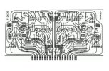
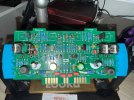
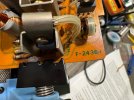
Below is what I found when I inspected my 881 driver board. You can see the damage to the traces on left and right side on bottom pic. Top side its hard to see in this photo bur there is some heat damage under some of the diodes on bottom left. Worth repairing? Wait and buy a used but cleaner F-2436 driver board for 881? Or buy new bare driver boards that Affinity for Artifacts sells on Ebay and build one?

Thanks for all the help! I'm pretty handy and am decent at soldering, but this would be my first recap project and am already learning so much from this site.

Front Driver.JPGrear driver.JPGlabel driver.JPG
 
Register to hide this ad
You can also find a "F-2436" board in the QRX 6001/7001 units. I have used a F-2436 board from a QRX6001 to get a 9090 unit working. I just used the 6001 board and used the factory parts list from the 9090 SM to build the driver for the 9090. It worked just fine. I did this modification after comparing the two 2436 pcb's which looked a little different but it was just the routing of a couple of traces. I noticed that two what looks like inductors [L01 & L02] are present on the 881 board but not on the 6001/7001/9090 pcb's. L01 & L02 are called out on the SM of the 881 as 2mH "Output Coils". The 881 precludes the 9090,8080 & 6001 so for some reason only the 881 has the inductors.

If you decide to try to build a 881 version of F2436 use the 881 parts list and keep the inductors. Look over the two boards carefully to verify the hoped for compatibility. Be prepared to bring the unit up carefully [Dim bulb mandatory]. If the dim bulb passes with the "clone pcb" your next hurdle is to see if you can bring the DC offset/bias in. If the unit can be calibrated you are most likely OK. At this point you should be good unless you have some distortion or other sound quality issues that may or may not be associated with the "conversion". Keep in mind that this is an experiment and may or may not be worth the attendant Risk/Benefit ratio involved. Your call on that!

If you want to try & need a 6001 board to work with I have a donor. Private Message [PM] me.
 
Hello there! Picked up a new to me Sansui 881 that needs some work. This is my first Sansui, as I just let go of my Yamaha cr-840 after getting tired of dealing with STK packs. The receiver works, and has no issues that I can see, but after opening it up to clean and de-oxit pots/switches I checked out the driver board and it looks like there has been some repairs due to some overheating issues. Also I was under the impression that the 881 used the F-2436 driver board, and inside my unit was the F-2436-1 which I believe is from a 8080 or 9090 unit? Either way, with all the damage and repairs I was going to rebuild/recap the board just in case but I then noticed the new driver boards on ebay.

Has anyone tried the new bare driver boards that Affinity for Artifacts sells on Ebay on an 881? I know the 8080 and 9090 boards are similar to the 881 boards minus the parts on the board, which I feel comfortable building after figuring out a parts list.

Below is what I found when I inspected my 881 driver board. You can see the damage to the traces on left and right side on bottom pic. Top side its hard to see in this photo bur there is some heat damage under some of the diodes on bottom left. Worth repairing? Wait and buy a used but cleaner F-2436 driver board for 881? Or buy new bare driver boards that Affinity for Artifacts sells on Ebay and build one?

Thanks for all the help! I'm pretty handy and am decent at soldering, but this would be my first recap project and am already learning so much from this site.
View attachment 3650595View attachment 3650596View attachment 3650597
I've built three of the bare boards and they're very good. Worth it if it's a keeper.
 
You can also find a "F-2436" board in the QRX 6001/7001 units. I have used a F-2436 board from a QRX6001 to get a 9090 unit working. I just used the 6001 board and used the factory parts list from the 9090 SM to build the driver for the 9090. It worked just fine. I did this modification after comparing the two 2436 pcb's which looked a little different but it was just the routing of a couple of traces. I noticed that two what looks like inductors [L01 & L02] are present on the 881 board but not on the 6001/7001/9090 pcb's. L01 & L02 are called out on the SM of the 881 as 2mH "Output Coils". The 881 precludes the 9090,8080 & 6001 so for some reason only the 881 has the inductors.

If you decide to try to build a 881 version of F2436 use the 881 parts list and keep the inductors. Look over the two boards carefully to verify the hoped for compatibility. Be prepared to bring the unit up carefully [Dim bulb mandatory]. If the dim bulb passes with the "clone pcb" your next hurdle is to see if you can bring the DC offset/bias in. If the unit can be calibrated you are most likely OK. At this point you should be good unless you have some distortion or other sound quality issues that may or may not be associated with the "conversion". Keep in mind that this is an experiment and may or may not be worth the attendant Risk/Benefit ratio involved. Your call on that!

If you want to try & need a 6001 board to work with I have a donor. Private Message [PM] me.
Thanks for the input. Over the holiday break I took some time and followed the traces on my board as well as the new blank F-2436 boards on ebay. They match up almost perfectly except for three places. The boards on ebay built by Hipocrates and Affinity for Artifacts were designed to match the 8080/9090 driver board AFTER the service bulletin mod was completed, so Id have to reverse that myself if I want to use it.

First difference I noticed was where R901 and R902 are located (designator R55 and R56 on 881 schem). These will need to be moved to where the Fuse location is on the new board. Seems to be an easy fix since deleting the fuses is possible as they don't exist on the original 881 board anyway, and it was an addition from the service bulletin mod.

Second difference is R23 and R24 will be deleted. Another easy fix as they aren't present in the 881 board and no jumper is required.

Third difference is the one I'm having trouble finding a fix for. The coil inductors L01 and L02 are not present on the blank board, and I traced where they would need to go. On the left side of PCB, one post of the coil should be placed between R42 and R26 resistors but of course there's no free opening so I'm going to have to connect to either of those holes with R42 or R26.

My question is would it matter which hole I jump the coil on to? The R42 or R26 on that same trace? I've attached a picture for reference. Look for the yellow L02 or L01, one post will attach to the open space where the fuses would have gone, but the other post is where i question where to attach. The yellow curved line is where i will move R901 and R902. After making these changes, the board will be exactly like original 881 and I've already created the BOM to populate the new board with.


F2436BlankMOD.jpg
 

Attachments

  • Screenshot 2025-12-29 104942.jpg
    Screenshot 2025-12-29 104942.jpg
    152.8 KB · Views: 11
  • Screenshot schem.jpg
    Screenshot schem.jpg
    105.1 KB · Views: 11
Last edited:
I would make the changes you have suggested but for the inductors I would leave them off at first. Sansui dropped them from the driver board on the 9090. If you do not get the board to work without the Inductors then cross that bridge when the situation calls for the inductors.
 
Those inductors are part of a Zobel network to avoid oscillations, On modern designs they usually are close to the speaker terminals outputs as some sort of termination devices.
On 9090DB and 8080DB they are located on F-2656, for that reason are not present on the driver boards anymore.

Just follow the 881 schematic and make the changes that you see on the design.
 
Wondering if anyone has the time to help me double check this new BOM, as I've done my best at creating it for this new replica board but it’s my first time doing so. I've updated the BOM that Affinity for Artifacts included in his Ebay posting for the 8080/9090 and made all the changes needed for the Sansui 881 version on the F-2436, I tried keeping with same brands that he did as well.. I have a google spreadsheet link as well as a snapshot of it... BOM Spreadsheet BOM F2436 for 881 worried about the highlighted ones only

I know this is a big ask, but just wanted another set of eyes on it if anyone has a chance. Not looking for verification on correct values of each part on the 881 part schem/list, but more for accuracy in choosing the correct updated replacement on Mouser. Mouser just has so many choices and I did my best at finding options with same values as listed in the 881 schem. Thanks!

Edit: can’t seem to get a clear snapshot uploaded. Spreadsheet works though. Highlighted ones are the parts in question.

BOM.jpg


(C13,C14) .047uf 50v Same? double check might be higher https://audiokarma.org/forums/index.php?threads/sansui-881-low-frequency-protection.607894/80-MMK5473J50J01TR18
(C15,C16) .33uf 50v80-MMK5334K50J01L4
(C17,C18,C3,C4) 68pf 50v81-RCE5C1H680J0M1H3A
(C5,C6) 22pf 50v81-RCE5C1H220J0K1H3B
KSC2690AYS512-KSC2690AYS
(R13, R14, R15, R16 4.7ohm)(R43/R44 10ohm)(603-MFR50SFTE52-4R7) (603-MFR50SFTE52-10R)
(R19, R20) 8.2k .5W603-MFR50SFTE52-8K2
(R21,R22) 3.3k603-MFR-25FBF52-3K3
(R29,R30)100ohm603-MFR-25FBF52-100R
(R51,R52)10ohm 2W279-ROX2SJ10R
R901(R55), R902(R56) 4.7k 1/2W603-MFR50SFTE52-4K7 Move to location where Fuse is located on new blank board.
 
Last edited:
Edit: can’t seem to get a clear snapshot uploaded. Spreadsheet works though. Highlighted ones are the parts in question.
AK only use low resolution compressed images. Good for sharing general pictures not really for share technical images
C13,C14) .047uf 50v Same? double check might be higher https://audiokarma.org/forums/index.php?threads/sansui-881-
Not relevant. They are talking about C13, C14 on F-2437 not F-2436

KSC2690AYS
Use TTA004B/TTC004B for TO-126 devices.

Nothing wrong with your resistors.
 
Thanks for the input. Over the holiday break I took some time and followed the traces on my board as well as the new blank F-2436 boards on ebay. They match up almost perfectly except for three places. The boards on ebay built by Hipocrates and Affinity for Artifacts were designed to match the 8080/9090 driver board AFTER the service bulletin mod was completed, so Id have to reverse that myself if I want to use it.

First difference I noticed was where R901 and R902 are located (designator R55 and R56 on 881 schem). These will need to be moved to where the Fuse location is on the new board. Seems to be an easy fix since deleting the fuses is possible as they don't exist on the original 881 board anyway, and it was an addition from the service bulletin mod.

Second difference is R23 and R24 will be deleted. Another easy fix as they aren't present in the 881 board and no jumper is required.

Third difference is the one I'm having trouble finding a fix for. The coil inductors L01 and L02 are not present on the blank board, and I traced where they would need to go. On the left side of PCB, one post of the coil should be placed between R42 and R26 resistors but of course there's no free opening so I'm going to have to connect to either of those holes with R42 or R26.

My question is would it matter which hole I jump the coil on to? The R42 or R26 on that same trace? I've attached a picture for reference. Look for the yellow L02 or L01, one post will attach to the open space where the fuses would have gone, but the other post is where i question where to attach. The yellow curved line is where i will move R901 and R902. After making these changes, the board will be exactly like original 881 and I've already created the BOM to populate the new board with.


View attachment 3664438
Did you ever complete this and successfully test? Appreciate the verdict you arrived at..!
 
Did you ever complete this and successfully test? Appreciate the verdict you arrived at..!
Not completed yet. All parts have been ordered, but haven’t had time to get it done yet! I’ll keep you guys up to date when I start testing.

Life caught up to me and it’s been tough to get into the shop with an 8 month old kiddo.
 
Not completed yet. All parts have been ordered, but haven’t had time to get it done yet! I’ll keep you guys up to date when I start testing.

Life caught up to me and it’s been tough to get into the shop with an 8 month old kiddo.
Almost finished with the board. Just need to get the trimmers in and jumpers between R25, 41 & R26, 42. Will report back once finished and tested!IMG_3482.jpg
 
Back
Top Bottom