• The move to the new server is done. There are some software and database maintenance updates in process. This has us passing the hat around to help out. We appreciate any donations. Seriously, even a dollar helps. The payment page may be found here - https://www.audiokarma.org/support.html

Sansui 9090 help factory or previous repair mods?

quadmatrix82

AK Subscriber
Subscriber
Hi all, I’m in the process of refurbing a Sansui 9090 I’ve had in long term storage. I’ve come across two mods which I’m not sure if I should replicate in the restoration or bring back to original design and hoping someone can help

Last I used this was over a decade it worked however always had a hum and recently got in the mood to refurb it

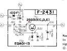
Power supply f-2431
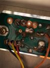
D901 10-d1 diode cathode was soldered to the positive of 470uf c901 in addition to its pad on the board.

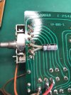
F—2541
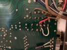
Someone has put a jumper wire 39 to I think 41? Has the red wire running to f05 photo attached

Any help would be appreciated thanks
 

Attachments

  • IMG_5438.jpeg
    IMG_5438.jpeg
    114.8 KB · Views: 18
Register to hide this ad
Power supply f-2431
D901 10-d1 diode cathode was soldered to the positive of 470uf c901 in addition to its pad on the board.
Looks OK according to the schematic, not sure what you mean by the bolded text above.

1741420486126.png

F—2541
Someone has put a jumper wire 39 to I think 41? Has the red wire running to f05 photo attached
Looks like some sort of non-factory kludge, (crappy soldering too!), if you can confirm the exact positioning (and where the red wire goes to), this might shed some light on what the link is doing.
 
Looks OK according to the schematic, not sure what you mean by the bolded text above.

View attachment 3447363


Looks like some sort of non-factory kludge, (crappy soldering too!), if you can confirm the exact positioning (and where the red wire goes to), this might shed some light on what the link is doing.
Thanks Hyperion for chiming in, the diode was soldered both to the cap and its own track solder pad I circled the spots in red

As for the other mod - it’s connected to pin 39 and 41, the red wire goes to fuse for on f-2546 3a fuse 39 goes to selector pot
 

Attachments

  • IMG_5448.jpeg
    IMG_5448.jpeg
    115.3 KB · Views: 15
Picture too dark to see what's going on, but providing there is 8V where it should be at 'B14' I wouldn't worry too much.
As for the other mod - it’s connected to pin 39 and 41, the red wire goes to fuse for on f-2546 3a fuse 39 goes to selector pot
Seems like that might have been an attempt (successful?), to get the dial lights to stay on with any input selected. See what happens when you disconnect the red wire? (Which fuse on F-2546?, what 'F' number?) - then try putting it back and disconnect the white wire. Watch for any changes in the operation of the dial lights when different inputs are selected.
 
Last edited:
Picture too dark to see what's going on, but providing there is 8V where it should be at 'B14' I wouldn't worry too much.

Seems like that might have been an attempt (successful?), to get the dial lights to stay on with any input selected. See what happens when you disconnect the red wire? (Which fuse on F-2546?, what 'F' number?) - then try putting it back and disconnect the white wire. Watch for any changes in the operation of the dial lights when different inputs are selected.
It looks to be that way the lights for the dial do stay on all the time regardless of the input I’ll reflow that solder will test further when I get it all back together Thankyou
 
The mod to the F-2541 is to keep the tuning frequency dial backlight on always. Normally the tuning frequency backlight is on only when the tuner [AM/FM] is active. There are some 9090 owners don’t like the backlight only on when listening to the radio. The other instance if the selector switch for that function is not working and the “always on” is a quick option to fix.

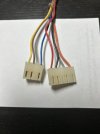
To make the conversion neater just move the red conductor 39 from the header on the other side of the pcb and plug it into position 41. The header plug normally is blank in position 41.

Attached is the OEM configuration of F2541. I would remove the white jumper and see if the switch can control the backlight. It if does you can leave it as OEM or do the jumper

IMG_1538.JPGIMG_1632 copy.JPG
 
Back
Top Bottom