• The move to the new server is done. There are some software and database maintenance updates in process. This has us passing the hat around to help out. We appreciate any donations. Seriously, even a dollar helps. The payment page may be found here - https://www.audiokarma.org/support.html

Sansui 9090DB Problems???

patfont

Super Member
Hi am new to the Sansui forum and have aquired an orphaned 9090DB. I am not used to working on anything this big and am having trouble even turning it over on my bench.
I powered it up on the dim bulb and got the bright light:yikes:

I pulled the 8 outputs and checked and 1 was testing bad. Tried again to bring it up on the dim bulb and she lights up but no relay click. Need to check relay operation and check P/S board and or Protection board furthur. Is there any known common problems in the 9090DB beast I should be looking at first. Thanks in advance for your help.
 
Register to hide this ad
Take a close up pic of the driver board, and indicate which channel had the bad output(s)
 
see thats the only problem with these big beauties, they try so hard to pack as much into the chassis as possible and loose track of what the thing is actually designed to do. These things are a royal PITA to work on much like the matantz 42xx series. Marantz is a fine example, everything from the 22xx series IMO is superior in every way possible to the 42xx series due to this very reason. I wish you luck friend, at the very least you will be quite buffed up after lifting this thing 20 or 30 times to flip it over hahaha.

I imagine hifi engine has the service manual for free if you don't already have it.
 
Take a close up pic of the driver board, and indicate which channel had the bad output(s)

Hi Paul thank you for taking a look.


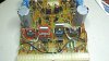
Wires from output trans of bad trans go to left side of board. If you click on this pic it will bring you to a page where you can view the original.
I went ahead and checked all 8 transistors on the left side and they are testing as good.
 
Last edited:
I am sure you know, but just incase make sure you remove the transistors from circuit to get a accurate result, after this I would check the diodes, again removing one leg from circuit.

If you still find no issues, replace the emitter resistors (should be low ohm like .5 or .47 ect, ect and be of high wattage 3-5 watts)

last important step is to recap that board and replace the output transistor, set bias and dc-offset and give it a try. I just had the exact same problem on a Marantz....one transistor in the output stage killed, and nothing else fried??? weird but there was a open cap on the driver board a 3300 uf. replaced that and the transistor and it works flawless again, took a bias set no problem and runs very close to 0vdc on the off-set side of things.
 
I am sure you know, but just incase make sure you remove the transistors from circuit to get a accurate result, after this I would check the diodes, again removing one leg from circuit.

If you still find no issues, replace the emitter resistors (should be low ohm like .5 or .47 ect, ect and be of high wattage 3-5 watts)

last important step is to recap that board and replace the output transistor, set bias and dc-offset and give it a try. I just had the exact same problem on a Marantz....one transistor in the output stage killed, and nothing else fried??? weird but there was a open cap on the driver board a 3300 uf. replaced that and the transistor and it works flawless again, took a bias set no problem and runs very close to 0vdc on the off-set side of things.

Thanks, well I am also very familiar with Marantz and what to look for in them but this is of a scale I am not used to see. However they all do operate the same. I have the driver board out so it will be easy enough to test the components. I would like to know which are the emitter resistors so I can check them also.
 
That is the older style driver board with the round transistors mounted on top of the driver transistors. I have circled it and the driver transistors that need to be checked. You will have to take them out of circuit to get the readings...

Be careful when pulling the round transistor, and mark the leads somehow as to remember where they go.

Keep in mind, this is only a starting point to see where we are at. There are plenty of parts on the board that must be replaced..Post your results. Also, take a better pic of the driver board so I can see all the components.

The Emitter resistors are mounted to the board behind the driver board. They are the big white ones. You can check these in circuit. They should all check around .5 ohms.
 

Attachments

  • 9090db.jpg
    9090db.jpg
    147.9 KB · Views: 189
Last edited:
On auto range all emitter resistors are between .3-.4 ohms (checked all 8)

TR09 (the round transistor) hfe 77 vbe .74V no leakage
TR11 hfe 51 vbe .62V no leakage
TR13 hfe 79 vbe .68V no leakage

So far all testing is good..........what would the next step be.

I did pull TR07 the transistor in front of the drivers and it also tests good:

hfe 151 vbe .78V no leakage.

I also pulled and checked the small ball shaped diode left side front and it is ok.

Pulled the 3 large ecaps on left side and they show proper uf.


If you click on the pic it will allow you to view the original size, let me know if it is good enough, or if I should break out the camera instead of using my phone.

 
Last edited:
Did you check all the fuses on the supply board??

Next step is to replace all the fuse resistors on the driver board (both channels). They are the dull colored ones standing up off the board. It will be impossible to read the color bands....

Look for the driver board page in the service manual. The fuse resistors are all listed as F.R.. These are the ones you need to change. There will be some way out of range and even open. You can get away with just replacing the ones that are out of range/open. You "should" use a metal film type and 1/4 watt is plenty good here.

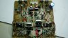
Next, I circled a little red diode in the pic. They need replaced with a series pair of 1N4148's for each.

Assuming you have the output(s) replaced, this should do it. Use your DBT and make sure you can adjust the bias. Once that is verified, turn the bias all the way down on both channels. You will have to use the meter for each channel, as the trim pots may work in the oposite direction for the other channel. You will need a meter with MA range and it takes the place of each of the fuses indicated in the adjustment procedure. You'll have to do one channel at a time, leaving the fuse for the other channel in place. Of course, don't make any connections or pull the fuses with the unit powered up. Then go to wall voltage and adjust it up.
 

Attachments

  • 9090DB2.jpg
    9090DB2.jpg
    140.1 KB · Views: 130
Last edited:
ooops sorry:whip:

I was using a 75W bulb by mistake (put in the 100W.) So now with the transistors and driver board out, the bulb goes dim and the 9090DB blinks red and turns green and the relay clicks.

Let me know if this changes any of the above post.

Thanks!
 
Nope. All the things I listed should be done to any 9090DB.

Also, you can use a nice little stacked film cap to replace the .47uf (orange) caps with...
 
Paul thanks a ton for walking me through this. I will try and get her up and running first and adjust bias and DC offset and let it play a bit. Then I would say a full recap is in order!
 
Here is what I am going to order: For the driver board

For the bad 2SD424:
MJ21194G (should I get a MJ21193G so it is a new pair?)
330uf 63V X2
470uf 6.3V X2
100uf 25V X2
.47uf 50V X2 (stacked film)
1N4148X4 (I have 1N4448) I think you can use either, I have used them to replace the same part on Marantz Phono Boards)
X14 FR resistors:
1/4 watt metal film
180 ohm X2
4.7 ohm X6
10 ohm X2
150 ohm X4
 
Everything looks great, but I would replace the entire channel with new On semi's.

Edit: Not a bad idea to replace all the trim pots with multi-turn types.
 
Last edited:
No worries. Once you get it up and running, you will be ordering more parts I assume.
 
ok parts have arrived, and I installed the 4 new outputs on the one channel:


The driver board had 14 resistors replaced and 8 e-caps, and the 2 VD1212's


Bias and DC offset are adjusted and I am now playing FM on my small mission work area speakers. Too heavy to carry up to the main system for now, maybe tommorow. The volume control is noisy so I hit it with deoxit. I am going to have to take some time and flush and clean and lube all the controls and switches. As a side note every light is working as well as meters. Gonna order some more parts and get this thing rebuilt, sounds very nice.

And again I would like to thank Paul for the guidance on this!

*******As a note for bias adjustment at the fuses, they are labeled wrong as far as channels go in the 9090DB SM.
 
Last edited:
Hello everyone. I hope I am posting this in an an appropriate place and I appologize if I'm not. I recently replaced the 1.5K R-12 resistor on the power protection circuit board of my 9090DB receiver. I also un-soldered and removed the 11 pin relay on the same board so I could open it up and have a look at the contact tips. I cleaned the tips with Caigs Deoxit and re-installed it. Now I have the green LED lighting up like its supposed to. Another problem has developed now however which I'm not sure how to fix. I still have the tuner assembly removed from the unit. I powered up the receiver with the volume control set to its minimum just to test the power LED. No antenna and no speakers are connected to the unit. I noticed that the left channel power meter is not illuminated. The right one is. Is it possible I disturbed the components that control this? Or could it be coincidence that both bulbs in the left channel meter went out at the exact same time? I hate to reassemble the entire unit until this problem is resolved. I've looked at the back side of the meter but I'm not too sure how to get at the bulbs should I need to change them. Any help will be greatly appreciated. I am by no means an expert at repairing these kinds of things. I am a long time hobbyist. Thank you in advance. Best Regards, Jay Scott
 
Back
Top Bottom