• The move to the new server is done. There are some software and database maintenance updates in process. This has us passing the hat around to help out. We appreciate any donations. Seriously, even a dollar helps. The payment page may be found here - https://www.audiokarma.org/support.html

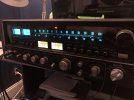
Sansui 990db/9090db DC on output

Rail voltage is +/- 61v If you're only getting 45v, something is wrong even on a DBT. Or it isn't rail voltage. Without clear photos, everything is just a shot in the dark.
And which F-2624 driver card version to you have? One has the STV-3H BIAS diodes, and the other (earlier) uses 2SC984 BIAS transistors and the layout is slightly different for some resistors.
 
What I did notice when attempting to bias the amps, the fuse holder for the good channel was drawing current (bias current, around 38mV) while the bad channel drew 0 across the fuse socket, no matter where the bias adjustment was.

Of course swapping the card 180, I could then bias the other channel on the amp card just fine.
I'm guessing that when you flipped the driver board 180°, your findings in post #20 with F01, F02 should transfer over to F04, F05. Is that the case?
 
Rail voltage is +/- 61v If you're only getting 45v, something is wrong even on a DBT. Or it isn't rail voltage. Without clear photos, everything is just a shot in the dark.
And which F-2624 driver card version to you have? One has the STV-3H BIAS diodes, and the other (earlier) uses 2SC984 BIAS transistors and the layout is slightly different for some resistors.
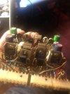
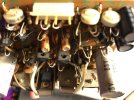
I’m actually using a DBT and a variac so it’s very possible that I’m just not getting full AC voltage to the unit. I was assuming it’s rail voltage as it’s the same voltage going into the output transistors on the healthy channel as well. I’ll grab pictures of it soon. Had to pack it back up to clear out my work station. I’ll attach a picture of what I have of the 2634 when I was rebuilding it.
I'm guessing that when you flipped the driver board 180°, your findings in post #20 with F01, F02 should transfer over to F04, F05. Is that the case?
I’ll have to check that out. I’ll let you know.
 

Attachments

  • IMG_6807.jpeg
    IMG_6807.jpeg
    108.3 KB · Views: 16
  • IMG_6809.jpeg
    IMG_6809.jpeg
    80.2 KB · Views: 15
  • IMG_6833.jpeg
    IMG_6833.jpeg
    147.1 KB · Views: 14
  • IMG_6793.jpeg
    IMG_6793.jpeg
    106.7 KB · Views: 13
  • IMG_6794.jpeg
    IMG_6794.jpeg
    99.7 KB · Views: 13
  • IMG_6795.jpeg
    IMG_6795.jpeg
    101.5 KB · Views: 18
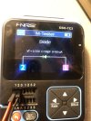
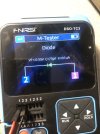
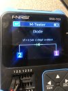
Pictures attached are what my LCR/everything meter says about those diodes I mentioned earlier.
 

Attachments

  • IMG_6832.jpeg
    IMG_6832.jpeg
    96.4 KB · Views: 17
  • IMG_6831.jpeg
    IMG_6831.jpeg
    92.7 KB · Views: 17
  • IMG_6830.jpeg
    IMG_6830.jpeg
    94.6 KB · Views: 17
  • IMG_6829.jpeg
    IMG_6829.jpeg
    148.4 KB · Views: 16
I’m actually using a DBT and a variac so it’s very possible that I’m just not getting full AC voltage to the unit. I was assuming it’s rail voltage as it’s the same voltage going into the output transistors on the healthy channel as well. I’ll grab pictures of it soon. Had to pack it back up to clear out my work station. I’ll attach a picture of what I have of the 2634 when I was rebuilding it.

I’ll have to check that out. I’ll let you know.
Yours has the 2SC984 BIAS transistors so change out those BIAS pots with 1k Bourns single turn. The 4.7k pots are for the DC Offset and 5k pots will be fine to replace them with.
A variac isn't needed, just the DBT for quick "shorts or no shorts" testing. I use a single 100w filament bulb for the 9090DB. But you can run smaller bulbs in series if that's what you have.
 
Closing out the thread with a victory.

A classic case of problem hiding in plain sight.. key word hiding.

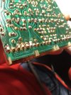
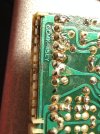
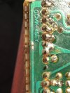
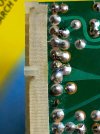
On the amp card, there is a shared pin between the very left outer pin to the right outer pin. On the amp card, the trace was blown/cut right underneath the plastic clips of the molex type connections.

This is going to the other channel as well, but since there is only a physical connection to the power pcb on one side, the severed trace prevented a connection from the power supply to the left side of the amp card.

That explains why it worked just fine with card swapped 180. Not a power supply issue after all. Made me do a recap on it at least, which it definitely needed!

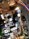
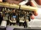
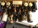
Pictures below..

Thanks all. Still testing here and there. Low channel on fm-am section, but aux/tapes sound good!
 

Attachments

  • IMG_7213.jpeg
    IMG_7213.jpeg
    133.3 KB · Views: 34
  • IMG_7215.jpeg
    IMG_7215.jpeg
    143.2 KB · Views: 33
  • IMG_7216.jpeg
    IMG_7216.jpeg
    144.4 KB · Views: 31
  • 73276695309__45241E40-C7BC-48C5-8568-D0D5B4841E2B.jpeg
    73276695309__45241E40-C7BC-48C5-8568-D0D5B4841E2B.jpeg
    86.2 KB · Views: 32
Last edited:
Closing out the thread with a victory.

A classic case of problem hiding in plain sight.. key word hiding.

On the amp card, there is a shared pin between the very left outer pin to the right outer pin. On the amp card, the trace was blown/cut right underneath the plastic clips of the molex type connections.

This is going to the other channel as well, but since there is only a physical connection to the power pcb on one side, the severed trace prevented a connection from the power supply to the left side of the amp card.

That explains why it worked just fine with card swapped 180. Not a power supply issue after all. Made me do a recap on it at least, which it definitely needed!

Pictures below..

Thanks all. Still testing here and there. Low channel on fm-am section, but aux/tapes sound good!
Yep, that's happened before. Some of the F-2624 have that area covered with tape that protects the trace from the plastic.
 
Back
Top Bottom