I will give it a try, but I am open to criticism if my answer is off.
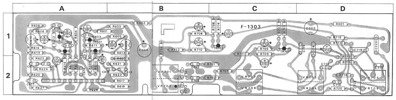
Capacitor 601 does not contribute because it is in series with the input, but then you have the miller capacitance of the first stage plus the series combination of C603 and C605 which are between the input of transistor Tr601 and ground.
Transistor 601 appears as a common emitter amplifier, so its gain at low frequency is G=Vout/Vin= - Rc/Re=180HOhms/(3.9+0.33)KOhms=-42.
Note that at high frequency, the 10uF capacitor on the emitter of Tr601 will start to become a low impedance and effectively it shunts the 3.9K resistor, which will increase the gain as the frequency increases. At DC the capacitor has infinite resistance, while at high frequency Zcap=1/Frequency*C. At 20KHz it will be a few ohms, so the gain becomes quite large, probably close to 400.
I could not get the datasheet for the transistor Tr601, and the only value I found for the output capacitance is 5 pF. So the maximum capacitance of the circuit, would be the sum of all the capacitances between the base of the transistor and ground, so we have a 68pF in series with the 10 uF capacitor, which would be effectively 68pF, and the miller capacitance, which in the worst case seems to be on the order of 200*5 pf~1070 pf. In the low frequency limit it will be closer to 300pF.
In the worst case, the 2.2K input resistance in combination with the 1070pF would form a low pass filter with a cutoff frequency of 67kHz.