HansVenlo
Member
More than a year ago I restored a Sansui AU-517 with a lot of help from Sansui specialist here on AK. It is still working fine.
A few months ago, I was able to get one for myself, as an upgrade from my Sansui AU-217.
It played OK, but not super. This was expected since it is more than 45 years old.
I found that a previous owner replaced the relay with an Italian one, but he put it on the solder side of the board. The pins were too big for the board and the solder pads were damaged. I ordered a new OMRON MY02-24V DC drop in and managed to get it working, on the right side of the board. I hate it when it is not original. But yes, the Power supply is a real PITA, to work on.
I restored the whole unit following the guidelines of Leestereo in his AU-517 and his AU-717 thread. Great read, that thread. Also read almost all of Hyperion's advices.
This is what I've done so far:
- Replaced all electrolytics and upgraded some of them, with Nichicon Fine Gold, Kemet and Panasonic.
- Replaced all VD1212 varistors with two 1N4148 in series.
Driver boards:
- Replaced C12/13 with film cap 1uF.
- Installed new Bourns Cermet pots.
- Replaced fusistors with 150W metal film resistors.
- Replaced zenerdiodes with Vishay 2% zeners.
- Replaced other diodes with 1N4148.
Equalizer:
- Replaced fusistors on equalizer board with 82,5W metal film resistors.
Power supply:
- Replaced all zeners.
- Replaced power caps with Kemet 15.000uF and Panasonic bypass 2,2 uF.
It did not work very well, because I found that a new zener on the right driver board was installed the wrong way around. Yes I know, check beforehand and afterwards. But I was very confident.
After that I tried to set DC offset and Bias. DC offset was very bumpy on the right board. One of the 2-watt resistors (R46) was 40% lower then stock (6,2W) instead of 10W. So I corrected the resistor.
I went the full monty for the power supply: replaced all big rectifiers and other small diodes and replaced TR01/02 with KSC1845 matched!
After correcting that Voltages were OK and very stable (+46,48 and -/-46,46 for left and +46,51 and -/-46,54 for right channel.
Bias was set for both sides, but DC kept on jumping all over the place.
I followed Leestereo’s advice in the 717 thread and had changed the R16 resistors in the driver boards to 27,4kW. I realised that was a difference with the 517 schematics, so I put the old 22kW back, which solved the running and jumping DC.
Starting up I noticed that the DBT did not go down in a straight line. Halfway down it flickers up for a moment and then further down. I found out that it originates from F-2722 Right Channel board.
After testing it comes out of protection when I keep Bias low (< 10mV), it plays a while and goes back in protection. But it is working at least.
F-2721 Bias test point: minus to chassis is minus 26mV.
: plus, to chassis is minus 11mV
F-2722 Bias test point: minus to chassis is minus 103mV.
: plus, to chassis is minus 86mV
I cannot explain these differences.
DC offset pre relay : pin 21 minus 10 to minus 14 mV
: pin 22 minus 92mV to minus 100 mV
I cannot explain these differences.
Checked all orientations twice and measured all resistors on the driver boards and the power supply. Everything seems to be OK. I changed the Driver board connections. F-2721 is playing fine, also with the other connections to the power supply, ButF-2722 is not.
After setting BIAS (rather low) and DC offset again, both channels play, but it sounds harsh.
I also measured hfe on Right channel driver board power powertransistors:
TR11 A899 hfe 157
TR08 C1904 hfe 115
TR05 A899 hfe 178
TR07 C1904 hfe 166
Could the difference between TR08 and TR07 cause my problems?Or the difference between TR11 and TR07?
I’m stuck, ran out of options, please can someone help me in the right direction?
A few months ago, I was able to get one for myself, as an upgrade from my Sansui AU-217.
It played OK, but not super. This was expected since it is more than 45 years old.
I found that a previous owner replaced the relay with an Italian one, but he put it on the solder side of the board. The pins were too big for the board and the solder pads were damaged. I ordered a new OMRON MY02-24V DC drop in and managed to get it working, on the right side of the board. I hate it when it is not original. But yes, the Power supply is a real PITA, to work on.
I restored the whole unit following the guidelines of Leestereo in his AU-517 and his AU-717 thread. Great read, that thread. Also read almost all of Hyperion's advices.
This is what I've done so far:
- Replaced all electrolytics and upgraded some of them, with Nichicon Fine Gold, Kemet and Panasonic.
- Replaced all VD1212 varistors with two 1N4148 in series.
Driver boards:
- Replaced C12/13 with film cap 1uF.
- Installed new Bourns Cermet pots.
- Replaced fusistors with 150W metal film resistors.
- Replaced zenerdiodes with Vishay 2% zeners.
- Replaced other diodes with 1N4148.
Equalizer:
- Replaced fusistors on equalizer board with 82,5W metal film resistors.
Power supply:
- Replaced all zeners.
- Replaced power caps with Kemet 15.000uF and Panasonic bypass 2,2 uF.
It did not work very well, because I found that a new zener on the right driver board was installed the wrong way around. Yes I know, check beforehand and afterwards. But I was very confident.
After that I tried to set DC offset and Bias. DC offset was very bumpy on the right board. One of the 2-watt resistors (R46) was 40% lower then stock (6,2W) instead of 10W. So I corrected the resistor.
I went the full monty for the power supply: replaced all big rectifiers and other small diodes and replaced TR01/02 with KSC1845 matched!
After correcting that Voltages were OK and very stable (+46,48 and -/-46,46 for left and +46,51 and -/-46,54 for right channel.
Bias was set for both sides, but DC kept on jumping all over the place.
I followed Leestereo’s advice in the 717 thread and had changed the R16 resistors in the driver boards to 27,4kW. I realised that was a difference with the 517 schematics, so I put the old 22kW back, which solved the running and jumping DC.
Starting up I noticed that the DBT did not go down in a straight line. Halfway down it flickers up for a moment and then further down. I found out that it originates from F-2722 Right Channel board.
After testing it comes out of protection when I keep Bias low (< 10mV), it plays a while and goes back in protection. But it is working at least.
F-2721 Bias test point: minus to chassis is minus 26mV.
: plus, to chassis is minus 11mV
F-2722 Bias test point: minus to chassis is minus 103mV.
: plus, to chassis is minus 86mV
I cannot explain these differences.
DC offset pre relay : pin 21 minus 10 to minus 14 mV
: pin 22 minus 92mV to minus 100 mV
I cannot explain these differences.
Checked all orientations twice and measured all resistors on the driver boards and the power supply. Everything seems to be OK. I changed the Driver board connections. F-2721 is playing fine, also with the other connections to the power supply, ButF-2722 is not.
After setting BIAS (rather low) and DC offset again, both channels play, but it sounds harsh.
I also measured hfe on Right channel driver board power powertransistors:
TR11 A899 hfe 157
TR08 C1904 hfe 115
TR05 A899 hfe 178
TR07 C1904 hfe 166
Could the difference between TR08 and TR07 cause my problems?Or the difference between TR11 and TR07?
I’m stuck, ran out of options, please can someone help me in the right direction?
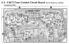
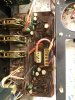
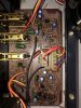

 . Thanks to DBT it survived this abuse more or less.