• The move to the new server is done. There are some software and database maintenance updates in process. This has us passing the hat around to help out. We appreciate any donations. Seriously, even a dollar helps. The payment page may be found here - https://www.audiokarma.org/support.html

Sansui AU-5500 Driver and PSU Board Recap

Zeus12

Active Member
Greetings Audiophiles,:)

Continuing with the recap of the AU-5500 just wanted to clarify what cap series would be best to use for the
F-2097B Driver and PSU Circuit Board. I am still struggling to "see" if it´s audio signal path.

To simplify things for myself, I follow this:
All small caps 1 and 2,2 uf -- I replace with WIMAs.
The Bi-polars with Nichicon Muse (green ones)
If not signal path: UPW -- If signal path (UKA, UFG, UES)
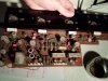
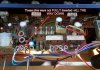
Driver and PSU Board.jpg

There were some mistakes in the Service Manual- C07 and C08 are 47 uf not 33 uf
F01-F04 Fuses are 4A instead of 3.5A (sticker on board)
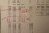
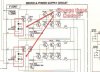
Service manual F-2097B.jpg

Can I use Nichicon UPW series for C05,C06 and C11,C12 (100uf 50V) or should I use an Audio grade (UFG/UFA) cap?
For cap C07,C08 (47uf 50V) should I use UPW, UFG/UKA or Bipolar? Cap C23 (470uf 6.3V)?


Cheers!!!:beerchug:
 
Register to hide this ad
I would use UPW for C05-06 and C11-12, they are decoupling caps.

I would go ahead and use UKA or UKL for C06-C07, since they are in or adjacent to the feedback network. They are 47uF 50V polarized according to the schematic. I agree with you that the parts List is incorrect about the value - if your unit actually had 47uF caps installed from the factory then that settles the argument, the schematic is correct. Also according to the schematic, they do not need to be bipolar unless you found bipolars installed from the factory.

I would use UPW/UPM for C23, protection relay delay circuit.
 
@GlasgowGrip

Big thanks!!:beerchug: Had I waited half a day I would have followed your advice from the start.

Used an Nichicon UFG series cap for C05-06 and C11-12, the decoupling caps instead of a UPW (high ripple) as you mentioned. Still trying to understand what a "decoupling cap" does exactly. Why is it getting "divorced" from the rest? :idea:

Will change those to a UPW and also C23 and C27. So to recap, haha :rflmao:,this is what is left to do as far as this board is concerned.
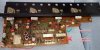
Sansui AU-5500_partial recap.jpg


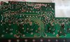
I cleaned the underside with acetone, it was very very dirty, then checked the Bias which was rock solid and the DC Offset and when I put it back together and - NO SOUND!!:whip::whip::whip:So depressed! What did I do wrong? Perhaps I shorted some traces? Have to say that it was such a pain to get those 7-8 caps of so out that I was sweating. Had to use solder wick since the leads were bent at a 90 degree angle making it impossible to use the desoldering gun. I was soooooooooooooo careful and took my time not to break another "eyelet"--learned my lesson from the Au-2900.
Sansui AU-5500_partial recap-driver board foil side.jpg


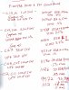
Will check tomorrow morning and get back. Thank God I didn´t continue recapping the Tone board (last one left). I know for sure it was working before so there HAS TO be something I did to this board. Checked the specs on the caps I replaced so far and this is what I got:

Sansui AU-5500_cap-values.jpg


Cheers!!!:beerchug:
 
Last edited:
...Used an Nichicon UFG series cap for C05-06 and C11-12...trying to understand what a "decoupling cap" does exactly...

Since you have already installed these capacitors, I suggest that you leave them in place. A "decoupling capacitor" can be defined as a power supply capacitor that is located on the close to the circuit to provide local filtering and counteract the inductance from the wiring/traces between the circuit and the main power supply. The bootstrap capacitors at C07/C08 can be ≥100uF.

...checked the Bias which was rock solid and the DC Offset and when I put it back together and - NO SOUND!!...

Does the relay close?
 
@Zeus12: First, I completely defer to @Leestereo, he is a true amp/preamp guru as far as I'm concerned. If he says C07/C08 can be increased in value, you can bank on it. It won't hurt anything to stick with the original value but he is a master at looking for mods that tweak the performance.

I also concur that you should just leave the UFG's in there for C05-06 and C11-12 if you already installed them. They'll work great, just kind of overkill in terms of quality/price to use FG's for decoupling duty.

As for troubleshooting, my first question was also going to be is the relay closing - you should see and hear it "click" after a few seconds?

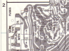
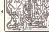
Beyond that, the cap measurements you listed seem reasonable, I wouldn't be concerned about them. I would be looking for polarity mistakes or soldering problems. Also double check you reconnected the board correctly, and double check the Pre-Main switch is set to Connected. All that being said, I can't see any obvious soldering problems in your photo of the PCB where you asked if you possibly shorted two traces. It would require more of a closeup, but as far as I can see it looks correct based on the board traces shown in the Service Manual on Page 9.
upload_2022-2-13_17-54-3.png

upload_2022-2-13_17-55-21.png
 
Thanks for your help guys!! Always a pleasure to get help from the true "gurus" of Hi-Fi. Will leave those UFGs in there then.

Yes, the relay closes normally, like before. :dunno: Speaking of relays, do they age? Like a life-cycle of "clicks"? Would it be a good idea to change the relay for a new one?

Will inspect the board again and check the soldering. I labelled and numbered all the wires and connectors so I don´t think it´s a cable connection. Checked the switch was on "connected". The pre-amp works for sure.

Cheers!!
 
Last edited:
Relay contacts can get corroded, oxidized and/or pitted, but don't see why that would all of a sudden start being a problem now if it wasn't before you started. And it wouldn't necessarily be both channels. But yes, you can change out the relay if you want to.

Check fuses - and did you reinstall fuses after setting bias? Any sound output through the headphone jack? Polarity on the caps you installed (not applicable to the WIMA's and the UES's) seems probably okay if you could set bias. Also, did you change out anything else - diodes, transistors, resistors?

Also, there is a troubleshooting chart in section 5 of the SM - never hurts to review it, at least check the power supply voltages that it mentions.
 
Last edited:
Good morning fellow audiophiles!

Oh, what a silly stupid mistake I made. Seems to me that I didn´t insert a couple of pins ALL THE WAY DOWN! Checked the fuses, bias and DC offset again--all OK. Connected my little testing speakers and IT´S WORKING!!! :banana::banana::banana:

Driver and PSU Pins.jpg

Will go ahead and finish this board, waiting for the Bipolars caps to arrive. Big thanks @Leestereo for enlightening me once again on the "bootstrap capacitors" at C07/C08 which you said can be ≥100uF. Would a 100uf 63V UPW cap be OK? Got that on hand. And big thanks @GlasgowGrip for "Also double check you reconnected the board correctly" You nailed it buddy!

So after this, I´ll have the tone board left. If I never use the tone selectors and keep all of them would a recap affect the sound? In other words does the signal bypass the tone board if not engaged?

Oh, how sweet it is to hear it sing again!!! Such a sweeeeeeeet, balanced, neutral and smooth model!! The mids are in another league. Again, from my limited Sansui listening experience.

This is all I did this morning--I´m sure you are all laughing your asses off at my rookie mistake. But hey, at least I didn´t lift any traces this time. Next time, I´ll MAKE SURE to DOUBLE CHECK the cables. PRACTICE MAKES THE TEACHER!

Cheers!!:beerchug:
 
Hey man, congrats on finding your issue - and no laughing at you, I'm sure we've all had those "doh!" moments, I know I have. Anyway, really glad you had a simple fix! These are such rock solid amps it's great to know that another one is getting back up to snuff.

So good question about the tone controls - there are amps that give you the ability to literally bypass the tone control circuits and yes this is one of them - S01 takes them out of the signal path when switched to "Defeat". However, it's very important to note that even though Sansui calls F-2414 the "Tone Control" circuit board, it is actually the Pre-amp board, so you just can't ignore it. Every signal passes through F-2414 and is amplified by it, so it's crucial to the overall sound and noise floor!

But hey, if you were really serious about the "what if I never use the tone controls"? Then you could theoretically ignore C11-C16. And at that point I'd say do some re rewiring so the Tone switch always acts like the "Defeat" position (remove wires from pins 48 & 56 on F-2414 and move them to pins 49 & 57, respectively). Anyway, if you're changing out C01-04 and C07-C10, then you might as well just change out C11-C16 and retain the option of using tone controls.

Big picture is not so bad, for F-2414 you're only looking at a total of 14 electrolytics that need to come out. C01-02 and C10-11 can be changed to films - MKS2's are fine choices, or use polypropylene if you have room to make them fit. C09-C10 and C13-C14 I would go with the UKA or UFG. Then just go with UKL for the rest (could even go UPW for C15-C16).
 
...on the "bootstrap capacitors" at C07/C08 which you said can be ≥100uF. Would a 100uf 63V UPW cap be OK? Got that on hand...

Yes, the 100uF 63V UPW capacitors can installed at C07/C08 if there is sufficient space on the board for them.
 
Hello again dear audiofriends!

Thanks for the help and guidance. Will do the complete Tone board -- just wanted to know how the audio signal path travels. Thanks for clarifying it @GlasgowGrip I wish I had "audio-signal" path vision - a la Superman´s X-Ray vision...:rflmao::rflmao:.

Did some listening this morning on it and it sounded GREAT!! After 30 minutes or so it just shut off by itself.:dunno: It was as if the power went off. It has done this once or twice before and I always thought it was because of having it plugged into a power strip, along with the PC, Tuner and another Au-2900. Could it be that it has only partially been recapped and the other components are supporting too much "stress"? A transistor? What about the diodes and zener diodes? Got plenty of replacements just in case. Ditto for some of the transistors on this board.

I noticed that even though the Bias is very easy to dial in and rock stable, the DC offset is very unstable and fluctuates wildly (more than other amps I´ve seen). So I thought, maybe the "trimpot" VR01-VR02 is defective or the D01-D04 diode from what I can see on the "Block Diagram".
Driver and PSU Board (Diodes D01-D04).jpg

I let it rest for an hour, turned it back on and worked fine again. As I said, it has done this one or twice but I didn´t give it much thought. Now it looks like it´s becoming a habit so want to fix it before it gets worse and spoils other components. "A stitch in time saves nine." This poor little thing is going to be 50 years old soon. I´m still scratching my head how it´s possible for it to still function after all these years. Old school is the best school!

Will finish recapping this board and up those "bootstrap caps" to 100uf. Open to guidance and directions for next steps.

Cheers!!!:beerchug:
 
...the DC offset is very unstable and fluctuates wildly (more than other amps I´ve seen)...

According to the schematic the differential input transistors (TR01-04) are 2SA726 types, these are known to be failure-prone as they age; they can be replaced with KSA992 (hFE matched pairs).
 
Hmmmm... When you say "shuts off by itself", can you describe the symptoms? The relay kicks in and cuts off the speakers? Does the power LED go off? I assume you're not blowing fuses. Is anything getting hot? Though I don't think this amp has anything like a discrete overtemp switch that would reset after it cools down... Assuming it's not something external such as the power strip, then based on what you said and assuming both channels are affected, I would be looking at the power supply section first. Check for funky solder joints, maybe there's a broken joint - or a broken component - something that opens up when it gets too warm?

Anyway, as for diodes and zeners on the Driver board, you can always change them, but generally if they measure good and you can set bias then they should be fine to leave alone. It's not unheard of for the DC offset to look "jumpy" on some Sansui amps - how much variation are you seeing? If it varies within 5 or maybe 10mV I think it's probably normal for that amp.

Otherwise, you should consider changing out the differential pairs (TR01/03 and TR02/04) with hFE-matched pairs of KSA992's. The 2SA726 are known troublemakers so usually best to just rule them out. The 2SC1124 are also known troublemakers and usually good idea to get them out of there as well, can sub them with KSC2690A or possibly others.
 
Greetings fellow audiophiles!

Thanks again @Leestereo and @GlasgowGrip ! Appreciate your guidance as always.

OK. Symptoms: Shuts off COMPLETELY -- Makes a fairly loud noise before (kind of an electronic/scratching noise, not a thumping/popping sound) and I don´t remember if the relay kicks before. Led goes off and if I try to flip the power switch on-off nothing happens. As if there is a general power outage in the house.

Have to unplug it, let it "rest" for an hour or two and then everything OK. The output transistors are not getting hot, I can touch the back "heatsink" with no problems. Regarding the DC offset --which is what I think is happening --the fluctuation is closer to 20mV +/- instead of the normal 5-10mV. Could that be the reason? Gonna keep the Diodes in there for the time being.

Anyways, I will change those 3 legged creatures (transistors), the (TR01/03 and TR02/04) with hFE-matched pairs of KSA992's and that way I can practice and learn something more about this wonderful hobby. It will also keep me out of trouble. :rflmao::rflmao: "The devil gives idle hands work". I´ll keep you guys updated.

Cheers!!!:beerchug:
 
Hi,

If the unit is shutting off - losing power as it the mains cord has been unplugged, then it just might be the actual mains on/off switch is causing your problem, these can go intermittent. As I recall the mains input switch is a lever toggle type, amd I believe that this is a double pole switch (two sets of contacts), with one pole/side not connected. If so try carefully swapping over the mains wires (and snubber capacitor) to the unused contacts on the other side.

Hope this helps

Cheers
John
 
Okay, thinking it through here... So there is a thermistor TS01 mounted on the heatsink and tied into the protection circuit, so theoretically that could cause the relay to open - but that would not affect the LED. There are two sets of windings in the transformer - one feeds the DC power supply section on F-2097 and one supplies the DC power supply section on F-2091 - you could confirm that both are affected simultaneously. But again, it really points to something very far upstream in the power supply - if the LED goes out along with the sound, and no fuses are blowing, then that says to me there is no AC into the Transformer. And assuming it's not some weird failure mode of the transformer, there's not much else upstream: the power cord, the power switch, a fuse, and the "voltage selector" (PU01 on the schematic, PU701 in the parts list), which is basically a plug and socket arrangement. Plus the wiring connections between them and the transformer. Anyway, next time it happens I'd take a hard look at the power switch and the voltage selector plug/socket and then go from there checking voltages going into and out of the transformer.

Good luck! - Steve
 
Greetings fellow audiophiles!

Thanks again @Leestereo and @GlasgowGrip ! Appreciate your guidance as always.

OK. Symptoms: Shuts off COMPLETELY -- Makes a fairly loud noise before (kind of an electronic/scratching noise, not a thumping/popping sound) and I don´t remember if the relay kicks before. Led goes off and if I try to flip the power switch on-off nothing happens. As if there is a general power outage in the house.

Have to unplug it, let it "rest" for an hour or two and then everything OK. The output transistors are not getting hot, I can touch the back "heatsink" with no problems. Regarding the DC offset --which is what I think is happening --the fluctuation is closer to 20mV +/- instead of the normal 5-10mV. Could that be the reason? Gonna keep the Diodes in there for the time being.

Anyways, I will change those 3 legged creatures (transistors), the (TR01/03 and TR02/04) with hFE-matched pairs of KSA992's and that way I can practice and learn something more about this wonderful hobby. It will also keep me out of trouble. :rflmao::rflmao: "The devil gives idle hands work". I´ll keep you guys updated.

Cheers!!!:beerchug:
Word of advice, ONE problem at a time - deal with the powering off problem first, when you have that nailed you can move on to other improvements. ;)
 
Greetings Audiophiles,

Thank you all for helping me out! Just did a quick check of some of your suggestions and this is what I saw:

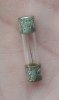
Fuses and Fuse Holders: All fuse check OK (beep) but one or two look to be a bit corroded (F02 especially, filament looks slightly discolored). I think I ordered one complete set from Mouser. Should I change them all even though they are still OK?
Sansui AU-5500_Fuses.jpg
Sansui AU-5500_4A_Fuse.jpg

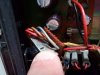
Regarding the mains on/off switch I checked and I really don´t understand what @skippy124 says "carefully swapping over the mains wires (and snubber capacitor) to the unused contacts on the other side". The wires are soldered on only one side, I don´t see where to solder them? I cleaned the switch with "Deoxit" and checked the solder joints which all looked fine.
Sansui AU-5500_Pre-Amp switch wires.jpg
Sansui AU-5500_Pre-Main Switch wires.jpg

Cheers!!!
 
Fuses and Fuse Holders: All fuse check OK (beep) but one or two look to be a bit corroded (F02 especially, filament looks slightly discolored). I think I ordered one complete set from Mouser. Should I change them all even though they are still OK?
I think the fuses still in the clips on the board look ok, but it wouldn't hurt to clean those fuse end caps and the clips with DeOxit, also re-tension the fuse clips to make sure they are gripping the fuses properly. The single fuse in the picture is junk, replace that one - the end caps have lost their plating.
Regarding the mains on/off switch I checked and I really don´t understand what @skippy124 says "carefully swapping over the mains wires (and snubber capacitor) to the unused contacts on the other side". The wires are soldered on only one side, I don´t see where to solder them? I cleaned the switch with "Deoxit" and checked the solder joints which all looked fine.
The picture you have posted doesn't appears to be the Mains Switch at all - it seems to be the 'connected/separated' switch. I still think the Mains Switch this is the most likely point of failure. To test this you should connect a multimeter (on Ω range) across the mains contacts, check they make and break cleanly, and wiggle the switch (when set to 'on') to see if it is in any way intermittent or has resistive contacts. These tests should be done (obviously) with the power off and the unit unplugged.

I goes without saying they you should be VERY careful when checking for the presence of mains power when the unit is in the fault condition, this may well be your next step after you have verified that all is well with the unit internally.
 
Last edited:
Back
Top Bottom