Zeus12
Active Member
Greetings fellow audiophiles,
I´m so in love with this model that as soon as I saw another on for sale, I JUMPED ON IT!! This one is in much better condition than my previous one. Oh, what a learning journey that one was. Got it fully recapped, changed the problematic transistors and it´s working like a charm!!!
https://audiokarma.org/forums/index.php?threads/sansui-au-5500-driver-and-psu-board-recap.987740/
For the 2nd one, I would like to do a full another recap and restore, improving and correcting my previous mistakes. It´s working great now and all parts seem to be 100% original.
Could someone please "enlighten" me and "correct" my homework? I would like to know what each cap is doing in the circuit and choose accordingly this time. I have tried to gather ALL THE INFO I could find from previous posts and recap projects, including those of the AU-5900 and AU-7700 since they share a lot of the topology.
I follow this rule to simplify my life:
All small caps 0.47ufs, 1ufs and 2.2 ufs etc. -- I replace with WIMAs.
If not signal path: UPW (UPM)
If signal path: UKL preferred. If not (UKA, UFG)
Bi-polars with Nichicon Muse (green ones)
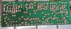
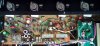
By the way, the board I have is the F-2097 and not the B version. Don´t know if that´s relevant.
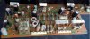
C01,C02 - 2.2uf 50V (orange caps) --Very important since they are the "Entrance" of signal into board - Change to WIMAs film or UKLs (low noise)
C13,14 - 1uf 50V (blue caps) -- Part of negative feedback? -- Change to WIMA film or UKL
C05,06 - 100uf 50V (black caps) --Local Decoupling caps. Can be increased? -- Change to UPWs (low leakage)
C11,12 - 100uf 50V (black caps) --Local Decoupling caps. Can be increased? -- Change to UPWs
According to the wonderful help of the master @Leestereo a "decoupling" cap is:
C09,C10 - 47uf 50V (gray caps) --Negative Feedback? Can be increased? Saw values of 100uf in AU-5900 --Change to UPW 47uf 63V
C25 - 100uf 10V BP (black cap) --Local filtering? Change to a Bipolar Cap, i.e. UES 100uf 16V/25V
C23 - 470uf 6.3V (gray cap) -- protection relay delay circuit (thanks @GlasgowGrip - Change to a UPW 470uf 16V/25V
C27 - 33uf 50V (gray cap) --Local Filtering? Change to UPW 33uf 63V
TR01,TR02 - 2SA726 Differential pair for Left Channel - Responsible for keeping DC Offset at 0 --Change to KSA992 (hfe matched)
TR03,TR04 - 2SA726 Differential pair for Right Channel - Responsible for keeping DC Offset at 0 --Change to KSA992 (hfe matched)
TR29 2SC1364 - Relay Driver Transistor - Can be changed to KSC260 or KSC945C
TR05, 06 2SC1124 - "Uniwatt" Style and can get "tired" - Can be changed to 2SC4793 - thanks @Hyperion
I didn´t see anything on "problematic" diodes or resistors that should be looked at. Of course, the "trimpots" can be changed to "Bourns". Anything else to look for?
Cheers!!!!
I´m so in love with this model that as soon as I saw another on for sale, I JUMPED ON IT!! This one is in much better condition than my previous one. Oh, what a learning journey that one was. Got it fully recapped, changed the problematic transistors and it´s working like a charm!!!
https://audiokarma.org/forums/index.php?threads/sansui-au-5500-driver-and-psu-board-recap.987740/
For the 2nd one, I would like to do a full another recap and restore, improving and correcting my previous mistakes. It´s working great now and all parts seem to be 100% original.
Could someone please "enlighten" me and "correct" my homework? I would like to know what each cap is doing in the circuit and choose accordingly this time. I have tried to gather ALL THE INFO I could find from previous posts and recap projects, including those of the AU-5900 and AU-7700 since they share a lot of the topology.
I follow this rule to simplify my life:
All small caps 0.47ufs, 1ufs and 2.2 ufs etc. -- I replace with WIMAs.
If not signal path: UPW (UPM)
If signal path: UKL preferred. If not (UKA, UFG)
Bi-polars with Nichicon Muse (green ones)
By the way, the board I have is the F-2097 and not the B version. Don´t know if that´s relevant.
C01,C02 - 2.2uf 50V (orange caps) --Very important since they are the "Entrance" of signal into board - Change to WIMAs film or UKLs (low noise)
C13,14 - 1uf 50V (blue caps) -- Part of negative feedback? -- Change to WIMA film or UKL
C05,06 - 100uf 50V (black caps) --Local Decoupling caps. Can be increased? -- Change to UPWs (low leakage)
C11,12 - 100uf 50V (black caps) --Local Decoupling caps. Can be increased? -- Change to UPWs
According to the wonderful help of the master @Leestereo a "decoupling" cap is:
C07,C08 - 47uf 50V (black caps) - Bootstrap Caps -- Change to UPW´s - According to the master again,A "decoupling capacitor" can be defined as a power supply capacitor that is located on the close to the circuit to provide local filtering and counteract the inductance from the wiring/traces between the circuit and the main power supply.
Used UPW 100uf 63V in my previous recap with no problems.The bootstrap capacitors at C07/C08 can be ≥100uF.
C09,C10 - 47uf 50V (gray caps) --Negative Feedback? Can be increased? Saw values of 100uf in AU-5900 --Change to UPW 47uf 63V
C25 - 100uf 10V BP (black cap) --Local filtering? Change to a Bipolar Cap, i.e. UES 100uf 16V/25V
C23 - 470uf 6.3V (gray cap) -- protection relay delay circuit (thanks @GlasgowGrip - Change to a UPW 470uf 16V/25V
C27 - 33uf 50V (gray cap) --Local Filtering? Change to UPW 33uf 63V
TR01,TR02 - 2SA726 Differential pair for Left Channel - Responsible for keeping DC Offset at 0 --Change to KSA992 (hfe matched)
TR03,TR04 - 2SA726 Differential pair for Right Channel - Responsible for keeping DC Offset at 0 --Change to KSA992 (hfe matched)
TR29 2SC1364 - Relay Driver Transistor - Can be changed to KSC260 or KSC945C
TR05, 06 2SC1124 - "Uniwatt" Style and can get "tired" - Can be changed to 2SC4793 - thanks @Hyperion
I didn´t see anything on "problematic" diodes or resistors that should be looked at. Of course, the "trimpots" can be changed to "Bourns". Anything else to look for?
Cheers!!!!
Last edited:


 .
.