• The move to the new server is done. There are some software and database maintenance updates in process. This has us passing the hat around to help out. We appreciate any donations. Seriously, even a dollar helps. The payment page may be found here - https://www.audiokarma.org/support.html

Sansui AU-717 muffled sound and what was causing it

Jefft91

Active Member
Before I start, I'm writing this without the aid of a schematic, so I'm not listing component reference designators. If there are any questions about specific components, please ask and I'll go back and check.

I had an AU-717 on the bench this week. The owner reported it was going into protect mode. It had been repaired in the past, which fixed the problem for some time, and it started to fail again. I fired it on on my DBT, and it did not go into protect mode. Hmm.

I checked the DC offset on both channels. The left was less than 10mV, but the right was almost 200mV. I aligned both channels to less than 2mV and let it idle to check the bias. The bias on the left channel was very close to 20mV, but the right channel was less than 10mV. I adjusted both to 20mV +/-1mV.

I then ran test tones through the various inputs and every thing seemed to be working fine. I also power cycled to see if I could get the amp into protect mode but the relay consistently pulled in. Time for a listening test.

The sound I heard when playing music could be described as warm, lacking highs, slightly smeared, but not unpleasant. I wondered if this is what some people describe as that "vintage sound". I thought I would just listen and see if the sound changed with time. My thinking was that it had not been powered up for some time and maybe some caps would reform, possibly having an audible effect. I left it playing for a few hours and then turned it off for the night.

(to be continued)
 
Register to hide this ad
I powered it up the following day, and the sound was the same. My best description was it had a "dark" sound as compared to my own AU-717. What could cause this? I was guessing it needed a re-cap, which was not in the budget.

I decided to look at the two amp modules. The fist thing I checked were the fusistors. Both on the left channel measured within one ohm of 150. The right channel had one that was measuring over 1900. Not open circuit, but definitely way out of spec. The other one was close to 150 Ohms. I also spied some corroded leads on a few components near one of the large caps. I replaced both fusistors with 150 Ohm metal film types. I removed the cap near the corroded components to get to the site of the destruction. It measured around 340uF (should be 470uF). I then removed the other cap, thinking if one was cooked, they were probably both bad. I was right. I the removed diode D02 (IIRC) and a 0.22pf ceramic cap which had their leads heavily corroded by the glue. Both were replaced, along with the two electrolytics, which I replaced with 470uF, 63V Nichicon UPS series.

I then put everything back together and checked it with a signal generator on the DBT. Everything seemed to be fine, so I connected the amp to speakers, a CD and turntable. When I put on one of my favorite CDs, the difference was surprising. Despite the few changes, the sound was no longer dark or muddy. The stereo image came into sharp focus, the attack and decay of notes was very distinct and precise, and vocals were very clear. In short, it sounded as good as my completely restored AU-717. I played an LP through the phono input and the results were similar. Note that I did nothing to the power supply board nor the tone board.

I'm now curious which component(s) had the biggest impact on the sound. I suspect the fusistor was the primary cause. I say that because I repaired another amp module with two bad fusistors that had a huge impact on the sound. I'd be curious to hear feedback on this topic.

While doing some initial checks on initial power-up, I noted that one of the regulated supplies was a few volts higher than the other. I have no idea how this would affect the performance or the balance between channels. In any case, I hope to look into this further. As I recall, there's a resistor divider that sets the negative voltage rail relative to the positive rail. Can't remember exactly. Time to pull out schematics....
 
You need to completely remove the glue. I cannot stress this enough. The glue used to secure the larger electrolytic caps becomes corrosive with time. The time is up! The PS board has the glue, too. Look over all three boards carefully and remove all traces of the glue. Ream out any component holes involved, because the glue will be in the holes, too. I use a hot air tool for SMT work, set about 140-150 C, and a wooden stick. Then, I clean the area thoroughly with isopropyl alcohol, before reassembly.
There is a good post here on restoring/upgrading the AU-717.
https://audiokarma.org/forums/index...estoration-upgrade-of-a-sansui-au-717.641945/
 
I'm now curious which component(s) had the biggest impact on the sound. I suspect the fusistor was the primary cause. I say that because I repaired another amp module with two bad fusistors that had a huge impact on the sound. I'd be curious to hear feedback on this topic.
The fuse resistors will have made the biggest difference as when out of spec they starve the driver stages of current. When they are really bad the amplifier won't even come out of protection. (Which is often the event that triggers the owner to seek servicing ;) )
While doing some initial checks on initial power-up, I noted that one of the regulated supplies was a few volts higher than the other.
It's nice to get the regulated supplies symmetrical, and you are on the right track about how to do this. However it isn't that important as it should only affect pre-amp headroom at maximum volume, which you are only likely to see during bench testing. Ideally each channel should be close to +/-33V - I have seen restorations where these voltages have been as low as +/-31V or as high as +/-36V which is fine providing the connected electrolytic capacitor voltage ratings (stock=35V) haven't been exceeded. Note that the negative regulator 'tracks' the positive regulator, so resistor changes should be made on the positive regulator, this is usually enough to get them in the ballpark.
 
Last edited:
You need to completely remove the glue. I cannot stress this enough. The glue used to secure the larger electrolytic caps becomes corrosive with time. The time is up! The PS board has the glue, too. Look over all three boards carefully and remove all traces of the glue. Ream out any component holes involved, because the glue will be in the holes, too. I use a hot air tool for SMT work, set about 140-150 C, and a wooden stick. Then, I clean the area thoroughly with isopropyl alcohol, before reassembly.
There is a good post here on restoring/upgrading the AU-717.
https://audiokarma.org/forums/index...estoration-upgrade-of-a-sansui-au-717.641945/
Absolutely spot-on Rick. :thumbsup:
 
You need to completely remove the glue. I cannot stress this enough. The glue used to secure the larger electrolytic caps becomes corrosive with time. The time is up! The PS board has the glue, too. Look over all three boards carefully and remove all traces of the glue. Ream out any component holes involved, because the glue will be in the holes, too. I use a hot air tool for SMT work, set about 140-150 C, and a wooden stick. Then, I clean the area thoroughly with isopropyl alcohol, before reassembly.
There is a good post here on restoring/upgrading the AU-717.
https://audiokarma.org/forums/index...estoration-upgrade-of-a-sansui-au-717.641945/

Don't use metal to scrape with as it will damage the circuit board. Wooden sticks or plastic. I used plastic tools made for car trim removal.

61nj283XylL._AC_SX679_.jpg
 
Absolutely spot-on Rick. :thumbsup:
Thanks, John! I just restored an AU-717, and it was like a barn find. Mouse droppings and all! I wet cleaned everything with antibacterial cleaner, before rebuilding.
Some of the glue was still the pliable, lighter color. But the darker, “evil” glue was predominant, and took out a slightly different subset of driver board components on one board vs. the other.
Maybe I’ve just been lucky, but this is the first Sansui that I’ve found glue corrosion on, in well over a dozen restorations. But everything I’ve worked on up to this point has been older vintage.
 
I
Don't use metal to scrape with as it will damage the circuit board. Wooden sticks or plastic. I used plastic tools made for car trim removal.

61nj283XylL._AC_SX679_.jpg
I have that same kit! It’s great for pulling splined shaft knobs, too. I bought some of those wooden sticks, called orange sticks, in the manicure tools at the local Walmart. They work great, too.
 
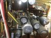
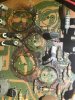
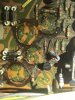
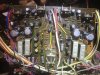
Thanks everyone for your inputs. I pulled F-2663 (power supply board) to check out the cause of the imbalance in the two sets of regulated supplies. I was greeted by lots of corrosive glue as you can see in the photos. After removing the electrolytic caps and any corroded components (10 resistors, a diode and a ceramic cap, in addition to all of the electrolytics on the board), I removed all of the glue. I used a combination of solvent and mechanical removal. I soaked some cotton balls in lacquer thinner and laid them over the glue to soften -- my electronic "spa treatment" -- and placed them over the glue covered areas. After a relaxing soak, I used a wooden stick to scrape off the softened glue. With the glue removed, I replaced the resistors and diodes before soldering in new capacitors.

Out of curiosity, I measured all the removed caps, and every one was out of spec, including eight that measured open circuit. These eight were so dried out that their weight was noticeably light, as if they were hollow. Several others had also leaked electrolyte onto the board, and one had a "haircut" label - you know, when the plastic sleeve shrinks so much it exposes the top edge of the can. I'm amazed at how well the amp performed in this condition.

I also replaced both 13V zener diodes (ZD01, ZD02). This rectified (pun intended) the regulated supply voltages, which were measuring slightly high (+/- 34-36V) before the rebuild. I also replaced all the electrolytics and the stabilstor (replaced with two 1n4148 in series) in the protect circuit.

I re-adjusted the DC offset and bias voltages for both channels after re-assembly. The unit now plays fine, and has beautiful stereo imaging and resolution, and comes out of protect mode on every power-up.
IMG_4020.JPG IMG_4021.JPG IMG_4022.JPG IMG_4024.JPG
 

Attachments

  • IMG_4032.JPG
    IMG_4032.JPG
    109 KB · Views: 44
fuse resistors what did it the most .. that sansui glue is bad in itself .i remember finding it years ago and measuring its resistance with my meter . this was before i read about it .
 
It’s really fun work, isn’t it? :whip:
Have a good look at the contacts on the wire ends that terminate on both ends of the board. The legs of the heat sink mounted transistors, too. Mine had signs of corrosion on those, also. Not the greenish, fuzzy stuff. Just a grayish sort of fuzziness. I tried cleaning them some, but it didn’t help much. A little dab of Deoxit D-100 on each seems to have made them appear much better.
 
Are you referring to the crimp terminations on the end of the wires that solder into the board? If so, I've never worried too much about them. They're crimped to the wire, which should not corrode, and they're soldered into the board. Checking for and repairing any cold solder joints should keep these conducting. Or do I misunderstand what you're talking about?
 
working on them, the parts are usually worn. out of spec. working on 2 now and everything is way way off- must have been used a lot. that glue! it's evil. it's nearly impossible to get off without slowly scraping it off. seems like a hair dryer doesn't do it.
 
Are you referring to the crimp terminations on the end of the wires that solder into the board? If so, I've never worried too much about them. They're crimped to the wire, which should not corrode, and they're soldered into the board. Checking for and repairing any cold solder joints should keep these conducting. Or do I misunderstand what you're talking about?
No, that’s what I’m referring to. The part of the terminal that is on the component side of the board showed “something” on mine. Who knows what kind of storage conditions my unit experienced, though? Straight Deoxit D-100 seems to have helped.
 
No, that’s what I’m referring to. The part of the terminal that is on the component side of the board showed “something” on mine. Who knows what kind of storage conditions my unit experienced, though? Straight Deoxit D-100 seems to have helped.

So, I've been overdue for updating, but Jeff91 was working on this unit on my behalf. I've been pretty ill the last few days so I just haven't been able to get in here and discuss his work (and I'm still not great) but I will tell you that he got it done, it sounds fantastic, and he was really easy and gracious and just terrific to work with. If anyone needs similar work and you're in the Corvallis, Oregon area, he's a great go-to. We had a couple of mini panics when hooking it up here (right channel out? No, a plug came loose) and those kind of things, but once it was going, it was everything I'd hoped for. There's still some issues to address that is nothing to do with the Sansui-my Garrard 301 actually has far less hum with the ground OUT of the Sansui, which is a first, that wasn't the case with other amps-but also noticed if I kick the loudness button on, it's certainly a lot punchier but creates a lot feedback. He also mentioned the idler wheel? might need some work. But every other source sounds great, and once I can get the turntable to work with this well, it should be fun once again to spin vinyl. I just haven't been able to follow up yet since he was here.
 
At least on the Kenwood stuff of that age I work on, the glue is fine until a capacitor leaks. Seems the electrolyte travels through the glue (which is usually everywhere) and corrodes anything it touches. If the glue is light tan and flexible, the associated cap is very likely just fine and will test OK. Brown glue and corroded leads around a cap means it leaked, and will be out of spec and often obviously lighter that one the same size that didn't leak.

This is not to say that Sansui's glue is exactly the same, it may go bad on it's own, but this case again leads me to believe the glue is fine unless it gets electrolyte in it from leaking caps! All the dark brown corrosive glue is associated with capacitors that have obviously leaked electrolyte.

Another argument for whole-sale replacement of electrolytic caps after 30 or so years, why wait for them to start leaking?
 
Thanks for the update. Yes, it's so difficult to get off, that I just clear the component terminal areas. That glue in your pics, haven't seen it that bad. Good info. Best wishes.
 
Back
Top Bottom