• The move to the new server is done. There are some software and database maintenance updates in process. This has us passing the hat around to help out. We appreciate any donations. Seriously, even a dollar helps. The payment page may be found here - https://www.audiokarma.org/support.html

Sansui AU-717, too high voltage and hum from pre-amp solved, TR9&TR10 on F-2663

Magnus Back

AK Subscriber
Subscriber
I had a very interesting finding today.
The +/-35V out from the regulated power supply was closer to +/- 40V on both sides and there was hum on both channels.
The hum was originating from the pre-amp and not related to the power amp.
So I started looking at the Power Supply first to see why I had too high voltages out on BOTH sides.
I checked the zener diodes and resistors used to voltage divide to set the output voltage but they were all fine.
So I replaced TR9 and TR11 and the voltages went down to the correct levels.
Hum still remained on both channels.
I then replaced TR12 and nothing changed.
Last I replaced TR10 and the voltage was now correct on that side and the hum went away.
All these transistors tested fine.
I think I will always replaced TR9 & TR10 from now on. Maybe they should even be "beefed up"?

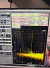
This is what the noise looked like (there's also a 1kHz sine added).
20260507_152407744_iOS.jpg
 
Last edited:
Register to hide this ad
Maybe there is something about the spec's of the expected originals (2SA847 & 2SC1708) or their replacements which is affecting, or being affected by, other nearby component replacements? - I know the modern replacements for the zeners ZD01/02 are a little different, giving rise (I think) to somewhat higher regulated voltages due to their subtle parameter changes?
 
Last edited:
I had a very interesting finding today.
The +/-35V out from the regulated power supply was closer to +/- 40V on both sides and there was hum on both channels.
The hum was originating from the pre-amp and not related to the power amp.
So I started looking at the Power Supply first to see why I had too high voltages out on BOTH sides.
I checked the zener diodes and resistors used to voltage divide to set the output voltage but they were all fine.
So I replaced TR9 and TR11 and the voltages went down to the correct levels.
Hum still remained on both channels.
I then replaced TR12 and nothing changed.
Last I replaced TR10 and the voltage was now correct on that side and the hum went away.
All these transistors tested fine.
I think I will always replaced TR9 & TR10 from now on. Maybe they should even be "beefed up"?
There are times when solder joints become fractured, but the cracks might be just too small to see with the naked eye.
Voltage regulators and other hot running parts typically expand at a higher rate than the cooler PCB, creating solder fractures.
I just fixed a Yamaha that used copper buss bars to distribute DC around the board.
One channel was intermittently out, but would come back when I flexed the board ever so slightly.
Once I narrowed down the location to a few square inches, I used my trusty Option-Visors to locate the fracture.
Turns out, many of the buss bar connections looked suspect, I touched them all up.
Clearly cooper expands at a different rate than fiberglass PCB's.
This was not the case here. All these were already tested and soldered back.
 
Maybe there is something about the spec's of the expected originals (2SA847 & 2SC1708) or their replacements which is affecting, or being affected by, other nearby component replacements? - I know the modern replacements for the zeners ZD01/02 are a little different, giving rise (I think) to somewhat higher regulated voltages due to their subtle parameter changes?
There might be but then it's something that only happens rarely. I have "recapped" over 30 of these by now and always replaced the zeners and very rarely those two transistors.
And I have never seen this amount of noise.

This is what I'm used to seeing from an AU-717. Note that no effort has really been taken to reduce external noise sources here.
And my reflection lately has been that MAYBE the +/- 35V in the AU-717 has more noise than it should have. "I wonder if that can be fixed".
Well from now on I will check these two transistors every time.
20260319_232612653_iOS.jpg
 
This is a Pioneer SX-950 receiver, much flatter and cleaner noise floor even though the peaks are higher.

1778799155902.jpeg
 
So I replaced TR9 and TR11 and the voltages went down to the correct levels.
Hum still remained on both channels.
I then replaced TR12 and nothing changed.
Last I replaced TR10 and the voltage was now correct on that side and the hum went away.
All these transistors tested fine.
I think I will always replaced TR9 & TR10 from now on. Maybe they should even be "beefed up"?

Looking at the original noise plot, it looks like it's all 60Hz and harmonics with the larger harmonics all full wave rectifier related multiples of 120Hz, so it seems like the power supply ripple is making it's way onto the +/-33V rails.

Is it possible that somewhere in the process one of the +/-33V supply wires got switched between channels? That might explain why the hum persisted until both TR09 and TR10 were changed. It looks like TR09/TR10 really does the bulk of the work in regulating 33V and TR11/TR12 is simply making -33V track the positive side and that's why swapping TR12 didn't do much.

Can't validate this harebrained idea now, no AU-717s in the house to experiment on :D

I checked and they aren't swapped. That part is odd, I have no idea why but. I checked multiple times to make sure the "hum" was identical.
I have another AU-717 I will check tomorrow (no hum) and swap TR09/TR10 and measure before/after.
 
Back
Top Bottom