• The move to the new server is done. There are some software and database maintenance updates in process. This has us passing the hat around to help out. We appreciate any donations. Seriously, even a dollar helps. The payment page may be found here - https://www.audiokarma.org/support.html

Sansui AU-719 F3098 Board Voltage problem

Assil

Member
Hi everyone
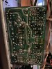
I am stuck with this problem as per attached photo resulting in that the right channel cuts off when switching the tone switch to ON.
I have replaced TR02 and TR04 with firstly C1815 and afterwards C1845f, and TR06 with same number (A992E), to no avail. I have checked the switches and all are ok. I have replaced the electrolytic capacitors and measured all résistances, no change, the fault remains.
No dry joint seen.
Please help

I aF51F3CCE-9AC2-4893-972D-BE0BA8B3CEDC.jpeg
 
Last edited:
Register to hide this ad
Hi,

Thanks for the added information. I didn't know what to say since all you had in the original post was hi and the picture. These guys will get you going in the right direction.
 
Last edited:
Check that TR06 is installed correctly. Also, check all transistors that have been replaced. What are the original transistors part numbers, and what did they get replaced with?

Rob
 
Check that TR06 is installed correctly. Also, check all transistors that have been replaced. What are the original transistors part numbers, and what did they get replaced with?

Rob
Hi Rob.. sorry I missed out the details which I have updated.
TR02 and 4 were C1313 which I replaced with first C1815 and then C1845F, and this brought no effect to the problem.
TR06 was A992E which I replaced with the same type.
I replaced all elec capacitors
I checked the power supply voltages and ground which look ok. I did not see a dry joint
I have redrawn the circuit with a pspice based simulator and tried to recreate the fault voltage levels but I cannot get the aforesaid voltages
 
Last edited:

Attachments

  • 0C33E914-EAC2-438A-BA96-520399FC1E3A.jpeg
    0C33E914-EAC2-438A-BA96-520399FC1E3A.jpeg
    140.1 KB · Views: 33
  • CAA071B8-0E5F-49C4-8639-E6D2175A4B97.jpeg
    CAA071B8-0E5F-49C4-8639-E6D2175A4B97.jpeg
    160.4 KB · Views: 32
  • BD64AD6A-731C-4B8F-B00A-744D565BD2A3.jpeg
    BD64AD6A-731C-4B8F-B00A-744D565BD2A3.jpeg
    109.7 KB · Views: 32
Hi Rob.. sorry I missed out the details which I have updated.
TR02 and 4 were C1313 which I replaced with first C1815 and then C1845F, and this brought no effect to the problem.
TR06 was A992E which I replaced with the same type.
It is possible that the pin order of the replacements is different from the originals, or that you simply did not install the replacements correctly anyway - we can't see this from your pictures. I have checked the pinouts and they do seem to be the same. But note that if you copied the transistor positions from the other channel to make them look identical, sometimes one channel has the transistors facing the opposite way to those in the adjacent channel.

The voltages you show on the schematic extract definitely suggests incorrectly installed transistors, with base and collector reversed perhaps?
 
Last edited:
Hi
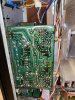
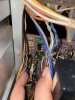
I am annexing photographs of TR02 / TR04 and TR06. You will see the pin orientation appears correct
 

Attachments

  • 61652CEA-836E-4B58-9C22-4A81B2D011EA.jpeg
    61652CEA-836E-4B58-9C22-4A81B2D011EA.jpeg
    92.1 KB · Views: 32
  • E16B5D25-2C40-44D8-9296-844B90A91FDE.jpeg
    E16B5D25-2C40-44D8-9296-844B90A91FDE.jpeg
    111.2 KB · Views: 30
I suggest you remove TR06 (for example) in the affected channel and check the pinouts with a multimeter or transistor tester.
 
I suggest you remove TR06 (for example) in the affected channel and check the pinouts with a multimeter or transistor tester.
I have removed TR06
Checked the pin out
1-emitter
2-collector
3-base
The transistor orientation is correct

I made another test today
I measured the voltage at the base of TR04.
It gradually raises from 16v to 22v
 
What is the voltage across R16 - 68KΩ ? - according to your voltage measurements it should be about 54 Volts.

I am VERY suspicious that the -29.7V isn't reaching the faulty channel... Have you changed any components on the F-3101 PSU PCB? - if so, what?
 
Last edited:
Yes R16 will read 55 volts approx
i have checked the -29.7 supply and it is present
The PSU appears ok. D/E and c/e power supplies are driven by the same circuit so any issue with it should reflect in both channels
I have taken more Points of measurements of voltage And that looks more confusing
Please check
 

Attachments

  • C9A36043-94C7-47F9-8B1D-A45DC7E633F7.jpeg
    C9A36043-94C7-47F9-8B1D-A45DC7E633F7.jpeg
    153 KB · Views: 16
Last edited:
Edited to correct inaccuracies
The PSU appears ok. D/E and c/e power supplies are driven by the same circuit
Correct.
so any issue with it should reflect in both channels
Correct.

On your diagram you say "Ground connected to chassis" - is the relevant ground on the power supply also connected to chassis? - that is pin 16 on F-3101 - where there appears to be 2 chassis ground connections connected together.
I have taken more Points of measurements of voltage And that looks more confusing
I agree, I have no explanation for what is happening, that is, if you have double checked all the information you have given so far.
 
Last edited:
Wrong - there are two distinctly separate regulated power supplies for the left and right channels
Wrong - because of my comment above.

Hi John,

The 719 has a common +/- supply for both left and right channels (unlike the 717).

It looks like the ground for the F3098 board comes from the respective driver boards and respective right and left channel RCA inputs (via a 10 ohm resistor in parallel with a 0.047uf cap at the RCA end.
 
It looks like the ground for the F3098 board comes from the respective driver boards and respective right and left channel RCA inputs (via a 10 ohm resistor in parallel with a 0.047uf cap at the RCA end.
So, maybe we are looking at an open R14 (10Ω) on F-3094 ?
 
Yes R16 will read 55 volts approx
i have checked the -29.7 supply and it is present
The PSU appears ok. D/E and c/e power supplies are driven by the same circuit so any issue with it should reflect in both channels
I have taken more Points of measurements of voltage And that looks more confusing
Please check

Hi,

Re the voltages that you have measured, can you please confirm the following.

Point G is effectively the base of TR04, and measured 20V initially, and lowers to 13,5V
Point H is the junction of R20, C14 and C16 and measured 0V.
Point F is effectively the base of TR06, and measured 27.7V.

Note that if I am reading the diagram you posted correctly, point H and point F are connected and should be at the same voltage.

Also, the voltage across R 24 looks like it is approx 57.4V, that would result in R24 dissipating approx 0.33W, - it would be getting rather hot, not smoking hot but "burning finger" hot.
 
Back
Top Bottom