• The move to the new server is done. There are some software and database maintenance updates in process. This has us passing the hat around to help out. We appreciate any donations. Seriously, even a dollar helps. The payment page may be found here - https://www.audiokarma.org/support.html

Sansui AU-777 Bias problem

Peter lye

Super Member
Hi all.
Seeking help from AU-777 expert, recently got a au-777(junk) from yahoo. 1st Power up test with 100w DBT, bulb light up in full. I did notice the cap C002 is Blown during visual inspection, and No fuses have blown.
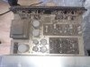
20210713_171118.jpg 20210713_171133.jpg 20210717_125222.jpg 20210717_223536.jpg 20210718_155342.jpg 20210718_155350.jpg 20210720_154428.jpg


After change out the blown C0002 cap with a new 6800uf/100v, I power up for the 2nd time and DBT when dim. So i hook up a pair of my test speaker and it sing without any problem. Took it off DBT, do notice both the TR811 & Tr813 start to heat up.

So I follow @stereofun post to measure the bias as below :

https://audiokarma.org/forums/index.php?threads/au-777-bias-adjustment.931281/
On the 777 the bias does not require a scope. You measure that by probing mA across the fuse holder for each channel, then set VR803/804 respectively for around 22mA

I think what you are referring to is "main amp section output adjustment" which is adjusted on VR801/802. This does require a scope. Normally there is a "good enough method" of adjusting 1/2 rail voltage on the output caps plus to ground - however on the 777's this is not straight forward. However for the 777, you can adjust for 39-40V (40-41V for the 777D) which is per schematic the voltage you should have en that position. It is not as precise as using a scope, but it will be the best you can do without, and will certainly be an improvement in case you find two different numbers say 37v in one channel and 42 in the other - just getting them alligned per schematic is a leap forward.

So probe output caps 825/826 - plus to chassis - adjust that to around 39V.

I can get VR804 to 22mA, But VR803 I Can't get it down 22mA ,lowest i can adjust is 80mA.

VR802 i can adjust to 39V, But VR801 can only go 27to 28V


Thank
peter
 
Register to hide this ad
Whith out a deep dive into your situation - I will say that your trimmers could easily be out of whack - looks like they were completely gunked up. I've had problems with my own 777a trimmers measuring well outside their range. The best thing to do is to have them replaced ! - But I understand if you just want to be able to get the amp dialed in so that its not smoking your output on the 80mA side.

So start up amp and identify which position is minimum bias, leave the trimmers there and turn off amp. The VR801/802 can be left in place, just note their current position. Next spray deox unto all the trimmers and work them vigorously in their full range. While at it clean all the switches and turnknobs as well. Start back up amp (with bias pots back in their minimum position, noted before), measure the bias on the 80mA side first and see if you can get it lower. If you cant, dont leave amp on. In order to figure out if it is your VR803 bias pot, you can compare its ohm reading to the "good" channel VR804. Here you measure on the two outer legs to see the pots max resistance which should be approx. the same between the pots (and correspond to the nominal rating in the SM). Next you can put the dial in the center position and see if they continue to measure roughly the same. If that looks good, then your bias issue lies elsewhere. Another thing that can mess up bias is if there has been output /driver replacements - so compare sides, look for an aftermarket replacement. There can be many other things hiding including out of whack, resistors, bias transistors etc.

Keep in mind, that you can never get accurate readings when on DBT - DBT is more a tool to see if shorts are present on amps that are new to you or you have worked on.
 
Last edited:
From your pictures, it looks like the power supply voltage is set up at 100V (Japanese, pic#5). If you are in the USA you need to change that first to 117V
 
Last edited:
Whith out a deep dive into your situation - I will say that your trimmers could easily be out of whack - looks like they were completely gunked up. I've had problems with my own 777a trimmers measuring well outside their range. The best thing to do is to have them replaced ! - But I understand if you just want to be able to get the amp dialed in so that its not smoking your output on the 80mA side.

So start up amp and identify which position is minimum bias, leave the trimmers there and turn off amp. The VR801/802 can be left in place, just note their current position. Next spray deox unto all the trimmers and work them vigorously in their full range. While at it clean all the switches and turnknobs as well. Start back up amp (with bias pots back in their minimum position, noted before), measure the bias on the 80mA side first and see if you can get it lower. If you cant, dont leave amp on. In order to figure out if it is your VR803 bias pot, you can compare its ohm reading to the "good" channel VR804. Here you measure on the two outer legs to see the pots max resistance which should be approx. the same between the pots (and correspond to the nominal rating in the SM). Next you can put the dial in the center position and see if they continue to measure roughly the same. If that looks good, then your bias issue lies elsewhere. Another thing that can mess up bias is if there has been output /driver replacements - so compare sides, look for an aftermarket replacement. There can be many other things hiding including out of whack, resistors, bias transistors etc.

Keep in mind, that you can never get accurate readings when on DBT - DBT is more a tool to see if shorts are present on amps that are new to you or you have worked on.

Hi thank you for your advice,
Had deox VR801 to VR804, now i can adjust VR801 to 34V max. but no luck with VR803,still 80mA+ min

Peter
 
Are you using step down tranaformer?
Thanks

use this 1000w
ST1000_ST1500_ST2000_01_1200x1200.jpg


Cheer
Peter
 
I think you should verify that TR807 & TR809 are OK, then check all the resistors around them including the 2 thermistors for value. When I say all the resistors I mean, R831, R833, R835, R837, R839, R843, R845, VR803 itself, and the 2 thermistors. The capacitors in that area are also suspect if they are leaky, C817, C819, C821. You can get an idea what's going on (without needing to check components one-by-one), by comparing voltages with the other channel. As already suggested by @stereofun :thumbsup:

This amplifier is an 'oldie' so a number of components could be out of spec'.
 
Last edited:
One suspect candidate certainly would be the TH803 on the left driver board. It's a thermistor - looks like a key part of the bias compensation as it sits right between the VR803's middle and outerleg. On "newer" amps this is done by attaching a transistor to the heatsink. Thermistors dont come with a specified resistance, since their resistance is highly dependent on temperature. But you can do two things, 1) compare the ohm value to the good channels TH804 - they should be about equal since they will be at same ambient temp. 2) if they show the same value, move a solder iron close,( no closer than a 1 cm) and see if they both change value like they should.

I assume you already probed VR803/804's as described (one of mine was out of range and prevented me from proper adjustment, so please rule that out first) - I also assume that you have verified that no aftermarket outputs or drivers are installed.

Other than that just unto @Hyperion test regiment as described. One trick here is to play "odd man out" when it comes to the resistors. Here you dont care about designated resistor values, all you do is systematically probe a specific resistors from good board to bad board, on at a time, and look for a difference of say more than 30%. I'd start with the driver boards.
 
Hi Peter,

I think you don't have to use the step-down transformer because this unit has select able voltage of 100v or 240v.

Thank,
Yes i know the 777 have multi voltage selector.
I have a rack of sansui gears full of 100v amp, i don't intend to have an odd ball that run on 240acv local voltage because I interconnected them by the ac point @ all the back of each amp. Sorry for about confusion.
 
One suspect candidate certainly would be the TH803 on the left driver board. It's a thermistor - looks like a key part of the bias compensation as it sits right between the VR803's middle and outerleg. On "newer" amps this is done by attaching a transistor to the heatsink. Thermistors dont come with a specified resistance, since their resistance is highly dependent on temperature. But you can do two things, compare the ohm value to the good channels TH804 - they should be about equal since they will be at same ambient temp.


Hi stereofun ,
the resistance for TH803 is 2.22ohm, where as the TH804 for the right channel is 8,16ohm.

Peter
 
I have zero experience with thermistors - just understand what they do, so I can't say if this is discrepancy is enough to cause the problem, however the performance of these thermistors would but crucial to your bias reading as I understand the schematic. If you are ok with a little experiment, I'd suggest you fire up your soldering iron and swap the two sides and then see if the 80mA min setting follows the swap. @Hyperion has quite a bit more experience, what says he ?
 
I have zero experience with thermistors - just understand what they do, so I can't say if this is discrepancy is enough to cause the problem, however the performance of these thermistors would but crucial to your bias reading as I understand the schematic. If you are ok with a little experiment, I'd suggest you fire up your soldering iron and swap the two sides and then see if the 80mA min setting follows the swap. @Hyperion has quite a bit more experience, what says he ?
had swap both thermistors, no change with the bias situation. that will rule out the thermistors. i changed the trimmer too and the bias reading still climb.R841 reading is way off compare to R842 .

peter
 
Last edited:
Great job, that rules out two components directly within the bias circuit.

So problem remains - bias running hot at 80mA in one side and it's trimmer can't bring it down. Does all outputs/ drivers in that side look original (or same as other side) ?

Have you run a quick and dirty odd man out diagnostic on all your resistors on both driver and main amp board, too see if one is very different from it's "peer" on the other side ? This could rule out the resistors, and up the diagnostic score card to: trimmers, thermistor, resistors, leaving only caps and transistors behind.

If not already, it would be very helpful if you have a transistor tester with three leads (check Amazon for some options) this will allow you to quickly run through your output and drivers to see if one is behaving out of range. Most of these testers will also check capacitors. Hard to do without going forward.

Just work systematically and figure out, which component on the 80mA side does not measure like the corresponding component on the good side. That's really it - then you can always swap that "suspect" side to side and see if fault follows.
 
Great job, that rules out two components directly within the bias circuit.

So problem remains - bias running hot at 80mA in one side and it's trimmer can't bring it down. Does all outputs/ drivers in that side look original (or same as other side) ?

Have you run a quick and dirty odd man out diagnostic on all your resistors on both driver and main amp board, too see if one is very different from it's "peer" on the other side ? This could rule out the resistors, and up the diagnostic score card to: trimmers, thermistor, resistors, leaving only caps and transistors behind.

If not already, it would be very helpful if you have a transistor tester with three leads (check Amazon for some options) this will allow you to quickly run through your output and drivers to see if one is behaving out of range. Most of these testers will also check capacitors. Hard to do without going forward.

Just work systematically and figure out, which component on the 80mA side does not measure like the corresponding component on the good side. That's really it - then you can always swap that "suspect" side to side and see if fault follows.


Thanks

Does all outputs/ drivers in that side look original (or same as other side) ?
all original parts, Sadly the TR807,808,809,810 is soldered.what the F........

R841 reading is way off compare to R842 .will investigate .

peter
 
Back
Top Bottom