• The move to the new server is done. There are some software and database maintenance updates in process. This has us passing the hat around to help out. We appreciate any donations. Seriously, even a dollar helps. The payment page may be found here - https://www.audiokarma.org/support.html

Sansui AU-D11II zener diode bypass question

Well, then I am right with not calming down about ~50+mV and wishing to get less! ))

In my opinion it was much easier to short the Power amps' (4266-67) inputs to ground and start the adjustment from the end (Power amp). Do you mean under "that provides a ground reference" that the input cable signal to Power amp has some offset even with no signal? - But specs of this signal is 0 +/-5mV then 0 is perfect. Or that the "ground" pin of the input signal connector is not wired with other ground on the board? But a thick ground wire is connected (shown red on the picture)

Снимок.JPG
 
Last edited:
Well, then I am right with not calming down about ~50+mV and wishing to get less! ))
It depends where you are measuring the DC offset - is this '50mV' measured from (Speaker Terminals) Hot (Red) to Cold (Black) OR from Hot (Red) to Chassis - this distinction is very important. Not acceptable in the first case - but definitely acceptable in the second case.
Do you mean under "that provides a ground reference" that the input cable signal to Power amp has some offset even with no signal?
It might do, but it will/should be minimal - see below.
You MUST adjust the DC offset for the F-4273 Tone Control Amp FIRST.
My experience of this adjustment (F-4273) is that it is easy to get 0V +/- 5mV or better.
 
Yes - I've succeeded to reach something close to 0 on F-4273, but it is also not stable and jumps and also so something else but only pots should be discovered. And I have something up to +/-50mV or more fluctuations between Hot an Cold terminals(
 
+1 to what Hyperion is suggesting above…I wouldn’t even bother to start troubleshooting knowing that there are parts installed in the unit from AliExpress .
I would Remove everything came from AliExpress and install the original if they are in working condition .
Mind that if you use 2SK170(x2) they should be match pairs in IDSS/gfs and thermally connected ….if not then your DC will fluctuate even greater …..
 
I have few original uPA68 and they behave absolutely the same. As for other parts - I just has 2 burned SV04 replaced by 4*1N4148 diodes. I may also return back 2*MV103 - the behavior with them is the same. And now I've disconnected the power from output stage and from Power amps. To test Control board only
 
Well, guys, thank you very much for support! As usually - I expected something scientifically complicated but happened as usually simple thing - bad contact in some power supply connectors :whip:
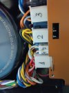
When I came to next step to Control board I found that multimeter shows about 0,7 Ohms betweeh theese 2 red pins and also between 2 blue pins. Then found that the pins are black - the silver is corrupted:

Снимок.JPG

Then I cleaned these pins as well as all anothers like these:

WhatsApp Image 2025-05-26 at 20.59.50.jpeg

And after that adjusted DC0 in the following consequence:
1) input of Power Amps (output of Control PCB);
2) Hot-Gnd
3) Hot-Cold

Then to my hapiness in one moment the annoying jumps were cancelled! Just slow floting now.

Then I noticed the following when I switched OFF and ON:
1) Hot-Cold started from 100mV and very fast countdown
2) The countdown slows during the countdown
3) as closer to 0mV and after ~10 minutes the countdown stopped and just slow floating remains.

But I suppose that this slow and small remaining range floating is due to the boards are not coated in the box, window with wind is close and this is just temperature floating (in narrow limits!) and while all boards beeing in the cabiten it will be more stable!

Besides I provided all DC0 adjustments under 80V (for safety) and didn't yet provided Bias adjustmets - I will do it when receive 1N4150 instead of 1N4148 (to replace 2 SV04 dead during the experiments) and when assemble all boards together. Next week

and - as previously I was based on AU-D11-II SM (20mV Bias there) and now kind people gave me AU-D907X-DECADE SM (43mV bias there) - might be bigger bias also improves the stability more?
 
Last edited:
doesn't the 907x use different outputs than the D11ii? I thought that's why the bias was different
 
yes! D11ii has 2SC3519 - 2SA1386 and 907x (decade too) has 2SC2922 - 2SA1216.
I can see no reason why the bias setting is different, the output circuitry is almost identical to the AU-D11 II, the rail voltage is the same, there are four Output Transistors per channel, which are standard bipolar types, and the bias is measured across two emitter resistors, which are the same values in both amplifiers. :dunno:

The output transistors in the Decade are higher power, AU-D11 II = 160V, 130W, 15A, whereas the Decade has 180V, 200W, 17A. rated types. :rockon:

There are two additional relevant things that are different when comparing models, one is that there is no rear panel Speaker Impedance switch in the Decade model, this switch (S13) reduces the rail voltage for lower impedance speakers on the AU-D11 II. And another is that there are double the number of main rail rectifiers in the Decade model, all these differences are clearly preparing this model for some 'heavy duty action' :)
 
Last edited:
And regarding the Bias (20 or 43mV) - if this is not a big matter (I guess not) - I would leave 20mV - just to less heating.
 
And regarding the Bias (20 or 43mV) - if this is not a big matter (I guess not) - I would leave 20mV - just to less heating.
If the SM says 43mV - then that's what you should set it to as I don't think it's a mistake, but it's also a case of try it and see - just in case it is a mistake/misprint. It might be that the higher bias setting leads to hotter operation than is wise, in which case reducing to somewhere closer to 20mV is an option.

The reason for bias current is to reduce or eliminate crossover distortion, the only way to know the ideal bias level is to monitor the amplifier on load, with a distortion meter while feeding a sine wave signal into it, then adjust bias for minimum distortion. The actual figure isn't all that critical providing the manufacturers recommendations are followed as closely as possible. My personal view is that anywhere between 20mV and 43mV will be fine with this amplifier, my AU-D11 II runs pleasingly cool at 20mV bias, but I would never increase this setting unless I had a very good reason.
 
Ough guys, this is not the end, I am so angry with Sansui and this "diamond" if it causes such monkey service!
Yesterday tonight I've finally assembled the amp and adjusted roughly. Everything seems was in limits, but I've noticed Rch Control Output is slightly jumping - up and down up to sometimes 10mV, while Lch just monotonously slowly decreasing and than closer to zero then more slowly - that's right.

Then I've replaced the FET diff pair SK389 in Rch by uPA68 (recently I did this few times and this is OK). After that Rch behave correctly as Lch.
I hope that'a all.

Снимок.JPG

But this morning before go to the office I switched the amp ON and connected multimeter and noticed unpleasant thing: In the very beginning when the amp was cold the measures were ~400mV (both channels) then they go down, passed through zero and then went to ~-40 in half an hour or about that. Then I had to go to the office. I have time to test only after office couple hours and holidays. - will provide a hour heating on Saturday.

Is this normal behaviour of cold amp? The thing is nobody heat the amp during an hour to start listen music! (P.S. Mistake - audiofiles do, but does it concernes this DC0 stabilising perioud?) And I remember that recently when I adjusted different amps I didn't noticed such behavior and such long stabilisation! But from another point of view - if the protection is OFF then it might be as it should be?
 
Last edited:
The final DC0 voltage extremely depends on (everything!): :mad:
- the room temperature;
- wind from open window (or/and condition air);
- with or without internal andf/or upper covers;
- if you just blows to the top cover holes by mouse

Just blowing to the top cover DC0 could shift to 100mV!
Is it normal?

While people in the forums desribe ready output amp boards for DIY that strictly keep 0.0mV ALWAYS and under any condition.
:dunno:
 
Last edited:
I can fire mine up & take some notes about what goes on. It hasn't been restored but I did bias it up a while back

which measurements are you concerned about?

iirc you need to set the outputs up without the preamp connected first, because the preamp will mess up your output settings
 
I can fire mine up & take some notes about what goes on. It hasn't been restored but I did bias it up a while back

which measurements are you concerned about?

iirc you need to set the outputs up without the preamp connected first, because the preamp will mess up your output settings
Hi!I mean DC betweek Hot and Cold.
Yes I've adjusted them correctly after 1.5 (OMG!) hours warming and stabilisation in correct order and conditions!

After that I've just blowed by mouse to the holes on the top and DC was icreased to 100mV :bowdown:
 
People say that solutions based on 1 crystall Power Amplifier Input Stage (like LME49830 Mono High Fidelity 200 Volt MOSFET Power Amplifier Input Stage with Mute) have absolutely stable as a stone zero and without any boring infinite adjustmets.
 
Just blowing to the top cover DC0 could shift to 100mV!
Is it normal?
I have just powered my AU-D11 II on with a voltmeter on the speaker terminals, and what was the reading from stone cold switch on? -0.3mV

After 5 minutes it is at 15.1mV, and rising very slowly. (blowing on the main amp board has almost no reaction, moves -1.3mV).

I'll note where it gets to here, after 30 minutes. watch this space.

20 minutes = 2.6mV
30 minutes = 5.2mV
 
Last edited:
in my case this morning when swithed on there are ~600 and ~400mV and after about 30 minutes of listening music on not big volume they became less than 1mV and stable. So I think that amp should work in some limits and if it is in limits then it's OK. And what concernes the SM adjustment - you just adjust ONCE and should not worry if it varyes later.
 
And what concernes the SM adjustment - you just adjust ONCE and should not worry if it varyes later.
This is correct, but... you should adjust it after 30 minutes warm up, because you want it at the ideal setting when in operation. DC offset will drift a bit, and it varies depending on the amplifier model, and the hardware status of the unit. In the case of the AU-D11 II, if you set the DC offset and then adjust bias (which will also drift and needs to be set after warm up), you do need to revisit the DC offset setting, because as I have said the two settings do interact a little - this is normal with many amplifiers, Sansui included.
 
Back
Top Bottom