• The move to the new server is done. There are some software and database maintenance updates in process. This has us passing the hat around to help out. We appreciate any donations. Seriously, even a dollar helps. The payment page may be found here - https://www.audiokarma.org/support.html

Sansui AU-D707F EXTRA Full Restoration

jeanpaul1812

New Member
Hi all

I’ve been a Sansui fan since I was a kid, mostly thanks to my dad. He always said Sansui made the best amplifiers in the world. Growing up, my dad had a Technics SU-7700, and I still remember those needles bouncing when the volume went up — that thing sounded really good.

Years later I went over to my uncle’s place (my dad’s brother) and he had a different “7700.” No needles this time, but the sound was on another level — super crisp and clear, and the bass was tight, clean, and well controlled, not muddy at all. That was the moment it finally clicked and I understood why my dad was always talking up Sansui. Yep, it was an AU-7700.

Just FYI, my dad still has his old Technics and my uncle still owns the Sansui. Those amps are pretty much eternal.

Anyway, that’s a bit of my background and how I fell down the Sansui rabbit hole. My first Sansui right out of college was an AU-719, which I restored a couple of years ago — I’ll start a separate thread on that one. I also own a D11 II and a D707F Extra that I’ll go into more detail on here, plus a couple of untouched AU-717s.

I’ve already started restoring one of the AU-717s to give to my brother as a gift. More to come.

The story of how I got this amp: I was searching for Sansui gear on Facebook Marketplace and came across this one in pretty rough shape. The top cover was broken, the side trim was beat up, there was rust all over, and the seller wanted $60 for it. He said one channel was out, and when you turned the volume up even a little, it would go straight into protection.

For $60, it felt like a no-brainer — a good deal and a good way to save this Sansui from being parted out. There’s a YouTube channel called Saving Vegas with the motto “Big or small, save them all,” and I pretty much applied the same principle here. Save all Sansuis! :D

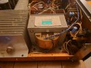
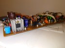
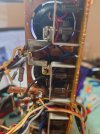
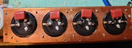
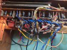
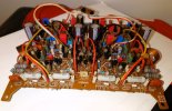
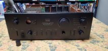
Here are some pictures of how this amp was ☹

During the week I will be adding more content so stay tuned!
s1.jpg20240327_025233.JPG20240327_025331.JPG20240327_025238.JPGs4.jpgs8.jpg
 
Register to hide this ad
Nice find on that Diatone "Sansui in disguise", it's a real rarity, even in Japan. I think there were 1000 made, if memory serves me correctly. Nice mention of Saving Vegas, too. I've watched some of his stuff as a now and again CV fan myself.
 
Hi all

I’ve been a Sansui fan since I was a kid, mostly thanks to my dad. He always said Sansui made the best amplifiers in the world. Growing up, my dad had a Technics SU-7700, and I still remember those needles bouncing when the volume went up — that thing sounded really good.

Years later I went over to my uncle’s place (my dad’s brother) and he had a different “7700.” No needles this time, but the sound was on another level — super crisp and clear, and the bass was tight, clean, and well controlled, not muddy at all. That was the moment it finally clicked and I understood why my dad was always talking up Sansui. Yep, it was an AU-7700.

Just FYI, my dad still has his old Technics and my uncle still owns the Sansui. Those amps are pretty much eternal.

Anyway, that’s a bit of my background and how I fell down the Sansui rabbit hole. My first Sansui right out of college was an AU-719, which I restored a couple of years ago — I’ll start a separate thread on that one. I also own a D11 II and a D707F Extra that I’ll go into more detail on here, plus a couple of untouched AU-717s.

I’ve already started restoring one of the AU-717s to give to my brother as a gift. More to come.

The story of how I got this amp: I was searching for Sansui gear on Facebook Marketplace and came across this one in pretty rough shape. The top cover was broken, the side trim was beat up, there was rust all over, and the seller wanted $60 for it. He said one channel was out, and when you turned the volume up even a little, it would go straight into protection.

For $60, it felt like a no-brainer — a good deal and a good way to save this Sansui from being parted out. There’s a YouTube channel called Saving Vegas with the motto “Big or small, save them all,” and I pretty much applied the same principle here. Save all Sansuis! :D

Here are some pictures of how this amp was ☹

During the week I will be adding more content so stay tuned!

View attachment 3684530View attachment 3684532View attachment 3684533View attachment 3684534View attachment 3684535View attachment 3684536

Thrilled to see this restoration. We don't see many of these getting restored here. And they are certainly worthy!
 
To carry out this restoration, I used the AU-D9 and AU-D907F Extra service manuals. I wasn’t able to locate the exact manual for this amplifier, but the AU-D9—especially—is very close to the AU-D707F, so it was a reliable reference. In addition, Hyperion’s AU-D9 restoration thread on here was extremely helpful and provided valuable guidance throughout this work.

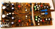
Power Supply / EQ Board Overview

This board not only handles the power supply, but also contains the equalizer section, and on the rear side, the moving-coil phono stage.

At first glance the board looked acceptable, but once removed it was clear it had seen heavy use—likely from its time in Japan. The areas around both regulator transistors were severely heat-stressed. Several capacitors in that area had dried out, particularly the 1000 µF units, and the PCB itself showed discoloration.

The 100 µF capacitors (C7 and C13) located next to the regulator heatsinks were noticeably bulged. Several small transistors nearby measured out of spec HFE, and many of the ½ W resistors were drifting 25–30% out of tolerance.
20240402_184125.JPG20240402_204019.JPG20240402_214753.JPG

Parts Replaced / Work Performed

  • All capacitors were replaced with low-ESR types, except C7 and C13, which were replaced with Nichicon UBT 125°C high-temperature capacitors due to the heat in that area.
  • Six capacitors originally in series were replaced using four bipolar capacitors.
  • Low-value electrolytics were replaced with film capacitors where appropriate.
  • All diodes, including all zeners, were replaced.
  • All ½ W resistors were replaced with metal film resistors.
  • The two MV-12 varistors were replaced with two 1N4148 diodes in series.
  • The four regulator transistors were replaced with MJE15032 / MJE15033, using fresh thermal compound.
  • All small transistors around the regulator area were replaced due to long-term heat exposure—no reason to leave stressed parts in place.
  • The original 4558D op-amp was replaced with a 4580DD, which I had on hand, so why not? :)
  • During reinstallation, 25-turn Bourns trimmers were installed for the equalizer section.
  • Phono selector switches were disassembled and cleaned (not shown in photos). All contacts were heavily oxidized/blackened.
  • All old solder flux residue was carefully cleaned from the board using anhydrous alcohol, leaving the PCB with a near mirror-like finish. :D

20240512_184218.JPG20240512_184233.JPG20240512_184021.JPG20240512_184108.JPG20240427_134406.JPG20240512_184233.JPG20240530_012428.JPG
 
Last edited:
Main Filter Capacitors & Bridge Rectifiers

Before removing any parts, I checked the bridge rectifiers with a multimeter. One of the rectifier diodes in the left channel tested shorted. I then checked the 2 W and ½ W resistors connecting the filter capacitors to the center junction, and found that one 2 W resistor in the left channel was open as well. This explained why one channel was reported as non-functional by the seller. Based on these findings, and without yet testing the output transistors, I’m pretty sure one is out :(. (more to come in the driver board thread so stay tuned ;))

While removing the bridge rectifiers to gain access to the main filter capacitors, I noticed that the cross-film capacitors in that area showed signs of heat damage. The epoxy bodies had become very brittle, almost glass-like, indicating prolonged exposure to high temperatures.

20240402_180432.JPG20240417_195053.JPG20240417_210820.JPG


Parts Replaced / Work Performed
  • The main filter capacitors were replaced with Kemet 15,000 µF / 100 V units. Due to the pin configuration, ring terminals were soldered to the capacitor leads to allow proper connection of the cross capacitors and the metal connector.
  • The cross capacitors were replaced with Panasonic polypropylene types of the same value. They were installed in the opposite orientation from the originals to reduce heat exposure from the bridge rectifiers.
  • The bridge rectifier diodes were upgraded to Vishay P600G-E3/E5 (Mouser part # 625-P600G-E3).
  • The resistors associated with each bridge rectifier were replaced with wirewound types.
  • The resistors connecting the main filter capacitors to the center junction were also replaced, using wirewound and metal film resistors.
  • Given the amount of heat damage found in this area, the goal here was to improve long-term reliability and reduce the likelihood of future overheating.
20240509_201545.JPG20240509_201559.JPG20240511_111519.JPG20240511_111526.JPG20240511_111542.JPG20240528_000652.JPG20240528_003229.JPG
 
Last edited:
Driver Board

Compared to the rest of the amplifier, the driver board was actually in pretty good condition. That said, I still measured a few ½ W resistors out of spec and found a couple of small-signal transistors with low HFE.
Unfortunately, one power transistor on the left channel was shorted, which I was already suspecting. If you look closely at the photos, you can also see that one of the 2SC2921s had been replaced in the past—the lettering finish is different from the others. Do you think that one could have been a fake? Ironically, that’s also the transistor that was shorted! o_O
Half of the board looks like it came straight from the AU-719, with the familiar small-signal transistor layout forming the diamond differential. The other half is part of the “new” Super FF circuit.
In addition to the service manual, I followed Leestereo’s AU-719 restoration thread, which proved to be an excellent reference since the AU-719 driver board is very similar to the one in this amp.
20240327_025233.JPG20240407_224826.JPG

Parts Replaced / Work Performed
  • Replaced the 4 main filter capacitors with 1000 µF / 80 V units.
  • All remaining electrolytics replaced with low-ESR types and Nichicon Muse & Gold.
  • Small-value capacitors replaced with film types.
  • All ½ W resistors replaced with metal film.
  • All diodes, including zeners, replaced.
  • Varistors (MV-103) replaced with three 1N4150 diodes in series
  • All small-signal transistors replaced with KSC1845, KSA992, TTA004B, and TTC004B, including the bias transistors. I chose to replace them all due to heavy use in the past and for long-term reliability.
  • Four emitter resistors replaced with wire-wound resistors of the same value
  • All trimmers replaced with 25-turn Bourns units
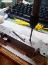
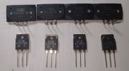
  • Power transistors replaced with Sanken 2SC3519 and 2SA1386. The main difference is the frequency rating: the originals were 60 MHz, the replacements are 50 MHz. Otherwise, the specs are very close. To install these, I drilled new holes in the heatsink and tapped them to match the original threads (see photos). In the end, the new transistors look like they came straight from the factory.:D
20240512_184256.JPG20240512_184302.JPG20240531_161430.JPG20240531_171042.JPG20240601_010215.JPG20241120_114055.JPG20240608_011811.JPG
 
Last edited:
Protection Board / Speaker Terminals

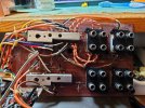
This board was also in good condition, except for two 2 W resistors that were badly bent—likely from a previous repair where the board had to be removed, and the past technician didn’t worry about damaging them. The speaker terminals were in poor shape as well, so I decided to do a modern replacement later.


20240410_162457.JPG
Parts Replaced / Work Performed
  • Replaced the main relay with an Omron MY4.
  • The other two relays were in good condition when removed, so I just cleaned the contacts.
  • Replaced all ½ W resistors, including the two previously damaged 2 W resistors.
  • Replaced all diodes.
  • Replaced all capacitors with low-ESR types.
  • Small-value capacitors replaced with film types.
  • Replaced all small transistors.

20240512_184734.JPG20240512_184741.JPG20240512_184751.JPG
 
Last edited:
Speaker Terminals

To fix the speaker terminals, I used the Duco USA-made ABS plastic sheet (1/8" thick, 8 × 12") from Amazon. I cut it to the same size as the existing binding post module. The holes in the back panel made it easy to locate and drill the new mounting holes.

I chose binding posts with short-threaded studs to fit within the spacing constraints caused by the relay. I used quality 16 AWG stranded copper wire, cut to length to reach from the protection board to the binding posts, and soldered everything in place. A bit of trial and error was needed to get the wire lengths just right.

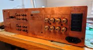
In the end, everything fit perfectly. If I ever need to remove the protection circuit in the future, there’s no need to desolder—just unscrew the eight bolts holding the new binding posts. If you look at the last picture, the new posts look like they came from the factory. I also polished the back side and added an IEC inlet plug socket for a cleaner finish.

20240526_222146.JPG20240526_230333.JPG20240526_230323.JPG20240526_230315.JPG20240528_012235.JPG20240420_164218.JPG20240528_005152.JPG
 
Last edited:
Tone Control Board & Speaker selector control

As you probably noticed in my first post, the treble pot was missing. The seller told me he wanted to get rid of this amp because he already had a AU-D707F (not the EXTRA) that was in better shape. Unfortunately, the treble shaft on that one broke, so he pulled the treble pot from this amp to fix his “better” unit. :cool:
Honestly though, $60 for the amp—even including the pot with the broken shaft—was still a great deal, so no complaints here.:cool::cool:

20240412_235631.JPG20240412_235642.JPG20240413_160240.JPG

What I ended up doing on the board:
  • Replaced all the caps with film caps and low-ESR types where appropriate
  • The two electrolytics (C9 and C10) that were in series on each side of the board were replaced with a single film cap
  • Replaced all the small-signal transistors
  • Installed a replacement treble pot: 100 kΩ, 1/8 W Bourns linear carbon pot
    • Model PBD182-K230K-104B
    • I went ahead and replaced the pair so everything would match

20240512_184810.JPG20240607_113652.JPG20240607_115132.JPG20250914_174122.JPG20250914_174143.JPG20260128_231317.JPG
 
Last edited:
Switches and Controls

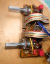
I went through and cleaned all the switches and controls in this amp. You can upgrade every electronic component with the best of the best, but if the switches are dirty, it’s like none of that work really matters. Dirty contacts don’t conduct current the way they were designed to, and that can cause all kinds of weird issues.
Below are a few pics of just some of the switches and selectors I cleaned. I also polished all the RCA connectors while I was in there.
20240414_141147.JPG20240414_141159.JPG20240414_141955.JPG20240414_145806.JPG20240526_171708.JPG
 
Switches and Controls

I went through and cleaned all the switches and controls in this amp. You can upgrade every electronic component with the best of the best, but if the switches are dirty, it’s like none of that work really matters. Dirty contacts don’t conduct current the way they were designed to, and that can cause all kinds of weird issues.
Below are a few pics of just some of the switches and selectors I cleaned. I also polished all the RCA connectors while I was in there.
View attachment 3687079View attachment 3687084View attachment 3687081View attachment 3687082View attachment 3687083

So impressed by how thorough you are!
 
Amplifier Cover

In my first thread there’s a picture showing the condition of the original case—or what was left of it. It really wasn’t a case anymore, just pieces of one. At first, I thought about peeling off the old wood-imitation vinyl and wrapping it with new material, but once I got into it, the MDF underneath was in terrible shape. There was severe damage, including signs of long-term exposure to humidity.
My guess is this amp sat in a damp basement in Japan for a long time, maybe with something heavy stacked on top of it.
The only part of the cover I reused was the metal top. I stripped off all the old paint and repainted it semi-gloss black.

I headed over to Woodcraft here in Cincinnati and wandered around the store until I found the perfect wood for the side panels of the amp. It just happened to be the same depth and width as the original panels, so I had to grab it. The folks at the store were super helpful and even cut it to the original length for me.
For the top panel, I used a piece of plywood, which I later darkened a bit to bring out the wood grain. I also bought stainless steel screws with the same diameter as the originals (which were missing) and oversized washers to keep the look close to stock.
In the end, I assembled everything using standard furniture hardware.
Honestly, I’m very happy with the results—it actually looks better than the original cover!

On the other hand, the faceplate doesn’t look nearly as good. It looks like rust has started eating away at the black paint on the sides, and there are scratches all over the top.
I’m planning to try repairing it—probably by lightly sanding the rusted areas with fine sandpaper and then repainting them with matte black—but I’m still open to ideas. If any of you have suggestions on the best way to tackle this, I’d really appreciate the input.
Also, if anyone knows of a faceplate for this amp in good condition, or knows someone who might be selling one, please let me know.


20260128_231719.JPG20260128_231729.JPG20260128_231750.JPG20260128_231616.JPG20250531_142550.JPG20250531_142605.JPG20250531_150633.JPG20250531_142446.JPG20260128_232441.JPG
 
Last edited:
Conclusions

At the end, I put all the boards back into the amp. I powered it on using a dim light bulb, and as soon as I switched it on, it passed with all green flags! Just a reminder—this is a Japanese amp, so I had to use a transformer to step the voltage down to 100 V.

After leaving the amp idle for about 20 minutes, I adjusted the bias and DC offset, including the adjustments on the equalizer board. Then I put the cover back on and started enjoying it!

Compared to the AU-719 I restored; this one has noticeably more detail. Don’t get me wrong—the 719 is still very warm and accurate—but this amp really digs into the nuances.
I tried it briefly against my D11II, but that wouldn’t be a fair comparison since the D11II isn’t restored yet. I’m pretty sure when that D11II is fully restored it will defeat the D707F Extra. :cool:

Now, when I compared it to a friend’s MA-5200, the Sansui easily sounded more detailed—and keep in mind, that’s a $3,500 amp! Mine cost $60… ;) and my friend even thought the Sansui beat his Macintosh.:p So maybe I’m a little biased towards Sansui, who knows haha.

20260128_231229.JPG
 
Last edited:
Back
Top Bottom