• The move to the new server is done. There are some software and database maintenance updates in process. This has us passing the hat around to help out. We appreciate any donations. Seriously, even a dollar helps. The payment page may be found here - https://www.audiokarma.org/support.html

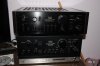
Sansui AU-D707X Decade

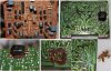
Next I worked on the power amplifier stage. I started by unplugging one connector on each of the driver boards, and one from the main board. Several of the wires on the foil side of the main amplifier board (F4296) were not looking good. I removed all 4 wires that bring the rails to the board (blue-red and yellow-grey) and all other wires coming into the board form the foil side. Then I unsoldered black ground wires 40 and 43 from the driver boards. Then I removed 4 screws that hold the entire assembly from the bottom side of the sub-chassis. The whole assembly comes out. In this amplifier board F4293 is revision 3 which concerns mainly with the ground connections (more variants on this in this thread), and the values of the trimmers for the bias adjustment (330 Ohms from factory). I removed the two driver boards and the two protector boards leaving the F4296 as shown here:
F4296_before.jpg
Only 10 electrolytic capacitors, and 4 of them with glue. After removing the capacitors, and cleaning the glue, i removed all 4 trimmers, carefully measuring their set point resistance. In their place I installed Bourns 25 turn 500 Ohms trimpots. The originals measured from end to end were more than 400Ohms, probably due to oxide at the joints between the pins and the ends of the tracks. The wiper and one end are soldered together in the board so the 500 Ohm trimpots will work fine. I measured resistances from the remaining pin to the wiper pin and they were all in the 120 Ohms +/- 15 Ohms. I set each new trimpot to the corresponding value of the initial trimpots and installed them.
Then I replaced the capacitors. I used 4x Nichicon UKZ 470uF 50V, 2x Nichicon UKZ 100uF 50V, and 4x Nichicon UFG 10uF50V.
F4296_after.jpg

I did not change the 27V 1W zener (it is supposed to be RD27F). I set the main board it aside and worked on the protector boards (F4268 and F4269), only two 100uF 6.3V electrolytic capacitors in series per board (C7 and C8). I used one 47uF 25V and a jumper wire in the location of C7 and a wire jumper in the location of C8.
I am not sure if there is any other component to replace here.
 

Attachments

  • F4296_removal_1.jpg
    F4296_removal_1.jpg
    183 KB · Views: 40
Driver Boards:
The F4267 and F4268 are very similar to the AU-D11II that use revision 2 of the driver boards. The schematics to use for this parts is that for the AU-D11-II except that there is no constant current diode in the drivers for the A-D707X but they use a 16V zener diode to set the current of the input differential FET pair. These boards have 6 electrolytic capacitors 10uF 35V. Also on the bottom side there is a 0.47uF film capacitor bypassing the 16V 0.5W zener diode (kdz1 i the AU-G90X schematic). This capacitor had glue applied on the foil side and this was starting to corrode the solder. I decided to first clean that up first.

F4267_initialWork.jpg

The glue altered the solder very noticeably. Using a solder wick i removed all the old solder and then I applied flux, and resoldered these points. Then I installed a WIMA 0.47uF rated at 63V (MKS4) bypassing the zener diode.
At this point I installed new 25-turn trimpots. The 100 Ohms original trimpots measured about 47 ohms for both driver boards. The 470 ohm trimpots (hot-to-GND adjustment) had the wiper and one end soldered together, and measured ~280 ohms from these common pins to the other end. I set the new ones to the exact measured values, and installed. Then installed 6x 10uF 50 volt Nichicon UFG capacitors, and cleaned the boards before reassembling the main amplifier section.

Using a dim bulb tester to turn it on the first time after this work, the amplifier came out of protection after some 10 seconds. Then I powered with full mains, and left i stabilize before adjusting the DC offset and bias. The hot-to-cold adjustment drifted after adjustment for several hours until I got it stable around 0.0+/-5mV. The hot to GND adjustment was impossible to get better than 0+/-500 mV, even after setting it to 0.0mV, after 10 minutes it was off again. I gave up and went on to check the bias current. These were easily to the 20mV reading between the emitters of the power transistors as the manual for the AU-D11-II requires. I ignored the 27mV that is stated o the AUG-90X service manual for the time being.
The amplifier sounds better than before recaping it, but its sound is different from that for the AU-D907. I like them both, but the bass for the AU-D707X Decade is clearly more pronounced. I did not use the loudness switch, and the tone control was disabled.

the hiss reduced slightly but it is still clearly noticeable. The hum was similar to the results i got after following Hyperion's recommendations in the posts above. I still need to change capacitors in the control board. I hope I can track the hiss and hum causes after that. I cross fingers...
 
The control board:

I took the control board (F4510) out of the amplifier, to replace the trimmers and the 10 electrolytic capacitors. Removing the board is quite involved. Once the top, bottom internal shieldings and front panel, and left side panel are removed, the only way i found to safely remove the front sub-panel was to set the amplifier on the edge of the bench to be able to remove one screw near the power switch, and two screws that secure the main amplifier assembly to the front sub-panel. Before doing this, I had to remove (unclip) the selector/equalizer boards from the plastic standoffs, remove the plastic bars that act on the input selector switches and all the connectors from the tape/record and magnetic input selection board. Also cut the cable tie near the magnetic input rotary switch, taking pictures of thiese wire manifold. Then with the front subpanel loose, removed the power switch and unplugged all the connectors on the left end of the control board. One 4 wire ribbon goes to the speaker protection board on the back and the other 4 wire connector goes to the speaker selector switch board. From the regulated power supply, I unplugged the connector that brings power to the control board. Finally remove the power indicator light (unclip standoff from front subpanel). The front sub panel can then be flipped on top of the amplifier.

RemovingControlBoard.jpg

At this point I removed the nuts holding the balance volume and tone potenciometers and the headphone socket. The final step to release the control board is to remove two plastic clips, one on the top side and one in the bottom side of the subpanel.
Then it is necessary to desolder two black ground wires(151, 152), and 4 coaxial signal cables (pairs of wires 38-39, 41-42, 95-96, and 93-94). It is very important to note how the wires are routed because there are ribbon jumpers in this board in addition to rather thick signal cables which make all this a tight pack of cables between the component side and the inner face of the front subpanel. Then the control board comes out together with the headphone and volume control daughter boards.

Controlboard_BeforeRecap.jpg

The AU-D707X Decade uses revision 1 of the board F4510. Thi includes the resistors on the primary side of the headphone transformers. The circuit as well as the component values follow the schematic of the model AU-G90X.
I replaced the 4 bypassing capacitors (100uF 35V) with Nichicon UFG 100uF 50V. Then there were two capacitors 47uF 16V bypassing the zener diodes. These were replaced with Nichicon UKZ 47uF 25V.
Then there were 4 10uF, 35V connected in pairs forming two bipolar capacitors that are in the negative feedback loop when the tone controls are enabled. I had three choices here. Install 4x 10 uF electrolytics back to back as in the original, 4.7uF bipolar, or use a flm capacitor. I went with the last option, because I had 10 WIMA MKS4, 4.7uF 63V which fit in this location. The only precaution I took was to select a pair of capacitors whose values were close to 5.0uF. The tolerance in these is 10% and I found two very close to 5.0uF. The electrolytics that I removed measured close to 11.2uF so I could have used a 5.6uF film capacitor but the diagram calls for 5uF.
Then I replaced two 100 Ohms trimpots. I used of the 1/4'' size (model 3266W). I measured the resistances and adjusted the new ones based on the percentage of the full swing, so the new ones did not end up in the same values but in this case this is the safest thing to do because the way the trimpot is connected in the circuit.
Controlboard_AfterRecap.jpg
At this point, considering the amount of work that is involved to take this board out, I decided to replace the 13V zeners because of the rather noticeable hiss that my amplifier had last time I tested it. I used 2% zener diodes (BZX55B13-TAP).
I applied contact cleaner to the potentiometers and switches.
The last issue was to take a look on the switch for the subsonic filter. It is a 4-pole double throw switch, so it has 12 pins. The switch was made by ALPS. Unfortunately the latching mechanism in this switch was damaged. Basically there is a ratchet on the side of the shaft that is pushed in to act on the switch. The ratchet no longer has the proper shape and the switch slips out after pressing it. Apparently this was not the result of mishandling it because the latch uses a small steel wire held by a leaf-spring and this can not wear-off the plastic of the ratchet because the spring force is tiny, so there is little friction. I speculate the switch was defective and it ended like this after regular use. The bad news is that I can not repair this switch. For the time being I put the switch back together and put it back on the control board. I am on the search of a replacement switch.

After all this, It took a good hour of work to put the amplifier back together. Then the standard dim-bulb test, unit comes back to life, and readjusted all the offsets. The DC offsets were much more stable after recaping this board.
The hiss is now less loud but still there. Now it is stronger with the tone control engaged. This is contrary to what I had before. The other thing I noticed is that If I fiddle with the tone control switch I can hear a bit of hum and louder hiss. This switch may need more cleaning. Now, at full volume there is always a residual hiss and a weak hum.
With regards to this board, it may be worth trying other capacitors in the tone control loop instead of the film caps i used. Also, there are a bunch of 2sc1845, which being early production, may be a source of hiss noise. If I get a switch to replace the broken one I will experiment with this.
I am listening to the amplifier now, and it sounds much better than when I bought it. It is very different from my AU-D907. It has the clarity of the AU-D907 but i think that the bass response is stronger. I love this sound. I will try to listen to it louder when my wife and kids are out. But I must anticipate that this is subjective, and neither my speakers nor my ears are good enough to say something comparable to the impressions of others.
Things to do towards reducing the hiss and hum:
Carefully check all the wiring and ground connections. Then I still need to determine if the main power supply should be renovated like @Hyperion and @LWB did. Also, it may be worth replacing the other 6 zener diodes in the equalizer, driver and power amplifier to see if this improves, and perhaps replacing the carbon film resistors in the negative feedback loops.
 
The inrush relay is missing but the board appears to have the tracks and pads implemented but they have not been populated with the components. The schematic appears to follow that for the corresponding board in the AU-G90X except for this missing components. Notably, looking at the pictures posted in the amp8 website, it appears that none of the AU-D707X have this inrush current control installed but the boards in principle support this circuit.

I was wrong on this. The AU-D707X and AU-D707X have the inrush relay and resistor installed from factory. It is the later released "Decade" versions of these amplifiers that do not bring this feature. Most likely cost cuts.
 
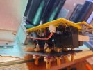
Just in case somebody wants to know this way or renovating the speaker terminals. Here is a cluster of photographs that I took while I was doing this.View attachment 1392001
Hi Jose thanks for having the foresight to post your solution. I think I like it more than what was suggested in the Hyperion thread you linked (although I was thinking the same thing initially - new fiberglass plate to hold new binding posts).

Your fix seems more elegant to me, and my Q is - did you just dremel/cut the expanded ends of the old posts in order to be able to screw them off? And then did you have to drill out the holes further in order to be able to get the new binding posts in? I wonder if this is doable without de-soldering the long metal strips from the pcb.


--

Second and unrelated Q - is there any 'at minimum' caps you would replace in this amp? My 607x has been worked on and runs well but I'm wondering if I should replace the large caps adjacent to the power supply, like what is often done in the first few generations of Sansui amps.
 
Okay, so even though the ends of the binding posts are peened, with a little bit of force they screw right out. Ended up using the drill for this.

Then I tried drilling out the post holes - they were slightly less than 3mm and need to be 4mm for the new binding posts, took me 4 steps - 7/64, 1/8, 9/64, 5/32. It worked while still soldered onto the pcb but I realized I was liable to cause damage or trouble and I ended up desoldering the posts. I had gone too fast when I was drilling out the riverted metal and the plastic around two of the pins got a bit melty. Always forget metal needs slow rpms.

Anyway the new binding posts are on the way, I picked the same kind as Jose, will know this weekend if it all works.


20250404_112358.jpg20250404_121026.jpg20250404_121038.jpg
 
Your fix seems more elegant to me, and my Q is - did you just dremel/cut the expanded ends of the old posts in order to be able to screw them off? And then did you have to drill out the holes further in order to be able to get the new binding posts in? I wonder if this is doable without de-soldering the long metal strips from the pcb.
I am sorry for my late repply. Family issues prevented me from being around. You have correctly figured these out by yourself, and you did it the same way i did. There is definitely no safe way to do this work without desoldering the long prongs from the printed circuit. And they are twisted and soldered so heat and untwist while solder is liquid, and then remove the solder with some wide desoldering wick.

For the capacitors, I do not have a list of what I used, but probably my choices were not always the best you could use. I did change the power supply capacitors, using the LKG types, exactly as Hyperion did on his AU-D11 II. The reason was that the LKG were being discontinued so i got 4 pieces and installed them in. I believe the originals were probably fine but changed them anyways.
Use UKL and liberally change all the smaller electrolytics in the main board, the tone control equalizer, and driver boards. The rest can be any good brand capacitor like panasonic FC, FM or some Nichicon, Rubycon or even film capacitors such as Wima or R82D from Kemet in locations where less or equal than a 4.7uF electrolytic capacitor was used. Clean all pots, and switches, remove power transistors, apply new thermal grease, and you will have a lovely amplifier.
I installed new zeners and trimming resistors but left everything else unchanged.
What I meant was, if I am NOT intending to do a full restore and change all electrolytics, then is there anything in particular that may be relatively high yield?
 
Hi all

I just want to share with the community what I did for the binding post for my AU D11II. I hope this helps you and others that want to restore this amp in the future. This amp is not fully restored yet. I only fixed the binding post and added an IEC320 inlet power plug. I can’t wait to start the full restoration, but work and life are in the way for now lol. Just FYI I did the same for my AU D707F Extra which is fully restored. (I know I owe this community a thread for my restorations including my fully restored AU719)

To fix the binding post I bought from amazon this “Duco USA-Made ABS Plastic Sheet 1/8 Inch Thick 8 x 12" then I cut it the same size of the existing binding post module. You can use the holes already cut in the back panel to reference the exact location of the holes you need to drill to add your new binding post. In this case I chose a binding post with a short-threaded stud for fitting purposes due to the spacing constraints because of the relay.

Then I used quality 16AWG copper stranded wire and cut it up to the limit of the relay and solder it to the protection board and the binding post terminals. I think the pictures will talk for themselves. You need to do trial and error at the time of cutting the wire to the desired length.

At the end everything fitted perfectly and If I want to remove the protection circuit in the future there is no need to desolder anything, just unscrew the 8 bolts holding the new binding post. If you look at the last picture those binding posts seem that they came from the factory! :D I’m very happy with the results. Let me know if you have any questions.
 

Attachments

  • 20240327_005918.JPG
    20240327_005918.JPG
    112.7 KB · Views: 20
  • 20240327_005924.JPG
    20240327_005924.JPG
    69.2 KB · Views: 18
  • 20240327_005950.JPG
    20240327_005950.JPG
    93 KB · Views: 18
  • 20240327_010003.JPG
    20240327_010003.JPG
    81.5 KB · Views: 20
  • 20240401_222603.JPG
    20240401_222603.JPG
    91.9 KB · Views: 17
  • 20240401_222613.JPG
    20240401_222613.JPG
    82.1 KB · Views: 19
  • 20240401_222626.JPG
    20240401_222626.JPG
    86.9 KB · Views: 19
  • 20240401_222636.JPG
    20240401_222636.JPG
    88.2 KB · Views: 19
  • 20240401_230445.JPG
    20240401_230445.JPG
    95.7 KB · Views: 19
  • 20240402_001645.JPG
    20240402_001645.JPG
    107.1 KB · Views: 20
Last edited:
Back
Top Bottom