GrisPato
Super Member
I took on an attempt to repair this amplifier for a fellow Sansui enthusiast living near by.
He bought the amplifier two years ago, restored.
Has been working fine up to some time ago when it would start with intermittent faults, no sound output.
Owner managed to get sound by working the speaker switches for a-b.
The last time it had sound output was on the B-terminals, A-terminals not working at all.
I asked him to bring it to do an easy check of DC-offset(s).
Then I found out the multifibrator is not active, no blinking/flashing light. Owner was not aware if it did before.
After checking DC-offsets and bias, right-channel was high, 170 mV, adjusted to close to zero. Hot/Cold to ground is not this close but doesn't go higher then 180 mV.
Bias was a little of on 3 of 4, 0 on the other. Because i don,t think this is causing the current fault i just left that for now.
Output from the protector boards on top of the driverboard is 0,7 V (pin 31,32), as far i can find info this means they are functioning as they should.
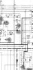
Measurements of the TA7317P also don't show any weird values for as far i can understand. Emitter of lQ1-2 have the 10 VDC.
The A-B speaker switches work.
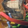
The only thing of I could find besides the protection light not flashing is that the replacement relais are rated just 5 ampere
He bought the amplifier two years ago, restored.
Has been working fine up to some time ago when it would start with intermittent faults, no sound output.
Owner managed to get sound by working the speaker switches for a-b.
The last time it had sound output was on the B-terminals, A-terminals not working at all.
I asked him to bring it to do an easy check of DC-offset(s).
Then I found out the multifibrator is not active, no blinking/flashing light. Owner was not aware if it did before.
After checking DC-offsets and bias, right-channel was high, 170 mV, adjusted to close to zero. Hot/Cold to ground is not this close but doesn't go higher then 180 mV.
Bias was a little of on 3 of 4, 0 on the other. Because i don,t think this is causing the current fault i just left that for now.
Output from the protector boards on top of the driverboard is 0,7 V (pin 31,32), as far i can find info this means they are functioning as they should.
Measurements of the TA7317P also don't show any weird values for as far i can understand. Emitter of lQ1-2 have the 10 VDC.
The A-B speaker switches work.
The only thing of I could find besides the protection light not flashing is that the replacement relais are rated just 5 ampere