• The move to the new server is done. There are some software and database maintenance updates in process. This has us passing the hat around to help out. We appreciate any donations. Seriously, even a dollar helps. The payment page may be found here - https://www.audiokarma.org/support.html

Sansui au777 oscilloscope settings

darai22jp

Active Member
Hello everyone.
After a lot of patience I was able to score an au777 with wood case. When it arrived I was surprised to see that no metal cover was under the woodcase...was the woodcase an option? No idea... inside was super dirty and a blown fuse. Checked the outputs... 1 of the d143 was blown and the 4000uf cap has been leaking.
After a complete recap and replacing the 2sd143 with d155 was able to set the current just fine. But I have no clue how to do the dc setting. I used to have an 777d which I set measuring dc across the
resistor of the outputs... worked fine but I never was confidently about that method...and it had a faulty volume pot as well, so I decided to sell it and look for another one until I was able to get this one.
About a year ago I was given a signal generator and an oscilloscope. So I thought I would be able to set the next 777 I get properly.
The service manual states to connect an oscillator at 1000hz my guess is that I needed to connect the signal generator at 1k in a sine wave signal but not sure about the frequency in hz...865582BC-E695-4A9C-880D-41BFC29CE923.jpeg
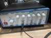
I connected it to aux 2 as stated being careful with polarity...but i don’t get a sine wave signal at the oscilloscope....
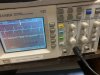
AD3596B3-6A33-465C-A439-4BC0EF08BFB3.jpeg
while increasing the volume a puff of smoke came out and thought I have blown the outputs... but it was the 10ohm 1/2w dummy I put at the speaker terminals.... so it was fine.... phew....
any ideas of what can be wrong? Pretty sure a lot, but any ideas would be really appreciated.
Thank you
 
Register to hide this ad
Hello,

The 777 is cap coupled right? There are ~2,200uf caps the block the DC before the speakers and there are no trimp pots for adjusting the DC offset.

From what I gather, your are injected 1k sine wave at the aux input right? Where are you probing with the scope?

Puff of smoke, you put a 1/2w resistor across the speaker terminals and turned up the volume? You need a much higher wattage 8 ohms resistor if you want to do that.

The goal with the sine wave from my simple understanding is to trace the signal (a volt or so) across the amp, mostly focusing on the tone and driver boards.

Measuring across the speaker terminals you need an 8 ohm resistor that meets or exceeds the wattage of the amp. I use two 8 ohm wirewound 300watt from Mouser. There of course are much more advance approaches.
 
Hello.
Thank you for your reply.
Probing with the scope from the speaker terminals looking out for polarity....
I will look for another resistor...
 
What is it that you are trying to do? Why do you want to put a load on the amplifier like that?
 
What is it that you are trying to do? Why do you want to put a load on the amplifier like that?
Hello
Is what the service manual specifies....
E7374478-1BF9-479A-819C-15FB14BA132D.png Right channel seems ok but the left shows up like this...
C83FC245-2611-4CA2-AFFE-E6F55582306E.jpeg
the top of the sine wave does not get completely flat... any Ideas?

thanks
 
That channel is distorting on the positive transitions and clipping on the negative peaks.
Something’s amiss...
Did you check the bias?
 
You're doing the right thing by using the scope, well done on finding your issue.

Here are some photos of a 5000x I did recently, maybe it may be of some help: https://audiokarma.org/forums/index.php?threads/5000x-recap.934300/

This looks stangley familiar, my first instinct would be to confirm voltages.

Below is a way to adjust the output without a scope. Can you confirm you are getting the ~80v from one output collector and ~half voltage on the other? Be very careful with the probes.

"Adjusting the output consists of adjusting VR801 to set the voltage on each of the output transistors equal. To do this:
a. Set VR801, if you're starting fresh, to the center of it's range
b. With volume at a minimum, turn on the power
c. Measure the DC voltage on the collector of the output transistor connected to the power supply (orange or red wire at the top of the F-6013 board, wire leading to the transistor), relative to a chassis ground. It should be 75-80 volts.
d. Measure the voltage at the collector of the other transistor (orange or red wire about halfway down the end of the board), adjusting VR801 until the voltage is 1/2 that measured above.
Repeat both adjustments, starting at the points found in the first iteration. Alternately, if you happen to have an 8-16 ohm, 60 watt dummy load and an oscilloscope, you can drive the amp, setting VR801 so that a sine wave clips, top and bottom, at the same level."
 
Thank you bubhardy for your reply.
current is stable at 21mA....
I assume that bias is within spec, since you have the SM.
But that waveform looks horrible.
Something weird’s going on with those positive going transitions.
The clip of the bottom can probably be fixed with that “output adjustment”.
Since your outputs are coupled through capacitors, you don’t need to adjust for a DC offset.
I’m not certain, but I think the output adjustment on these cap coupled units basically centers the output around the what I call the “midpoint” of the amplifier power supply. I’m working on a Sansui 4000 receiver right now-it’s cap coupled, and has the same output adjustment, but I haven’t adjusted mine because I can only supply 6 mA of bias max, and I’m trying to figure out what is limiting my driver boards.
Anyway, scope the driver board output, and see if it looks like that upper part of the trace. If it does, scope the input to your driver board, etc., and work your way back until you see a smooth sine wave. When you find a clean sine wave, the last stage you checked is where the problem is. Loos pretty non-linear, so it might be a transistor.
 
Hello
Is what the service manual specifies....
View attachment 2220464 Right channel seems ok but the left shows up like this...
View attachment 2220465
the top of the sine wave does not get completely flat... any Ideas?

thanks
Its actually going unstable, or something is breaking down under load which in turn is causing the instability.
I'd be taking the load off the speaker outputs and seeing if it still does it with no load on it.
This is completely safe and will not harm the amplifier at all.

Let us know what happens then....
 
Hello
After a lot of trial and error I found out that the problem was in the preamp section... hooked up my trusted CA606 to the 777 and I was able to get a more consistent wave in both channels... not perfect but good enough.
In the schematic specifies that there are (2) 2sd650 and (2) 2sd281 per channel in the preamp section but for some reason in mine there are (3) 2sd281 and (1) 2sd650... No idea if somebody was here bfr me, but doesn't look like...after some checking seems that the 2sd650 is failing so after looking for replacements I was able to find 2sd650`s in Yahoo Japan auctions so probably I will get them in a couple of days. I was also be able to find 2sd144`s at my local parts shop...the last 4, so I grabbed them. They will be a more suitable replacement for the 2sd143 than the 2sd155 I used before.
So I have to wait for parts to arrive. I will keep you informed in progress.

Thanks
 
Last edited:
Back
Top Bottom