Hello everyone!
I’d like to share how I made LED backlighting for the Sansui BA‑F1.
Please accept my apologies for the translation — I don’t speak English well.
I made new backlighting for the needle and peak indicators, as well as for the amplifier power button.
My goal was to:
make the indicators’ backlighting yellow, like in the original;
increase the brightness of the backlighting;
add a red backlight for the alarm mode.
I ran many experiments with backlighting colours and came to the conclusion that yellow is the most informative colour. With green and blue, the power scale and the red peak indicator are hard to see. Besides, these colours look unnatural — in my opinion, they’re rather ugly.
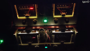
I have two such amplifiers: my custom backlighting is installed on the top one, while the bottom one has the stock version.
As you can see in the comparison, the top option is more informative — the needles, power scale, and peak overload indication are much easier to see.
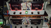
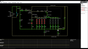
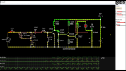
I also added red indicator backlighting that activates when the amplifier is powered on and when the amplifier’s protection circuit is triggered.
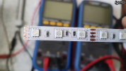
The new backlighting was implemented using a three‑colour (RGB) LED strip. I obtained the desired yellow colour by simultaneously activating the red and green diodes on the strip.
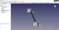
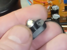
I designed and 3D‑printed the backlight holders.
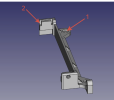
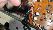
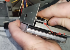
I installed the holders right where the original backlighting was — there are mounting points for that, marked with arrow 1.


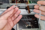
An aluminium profile fitted with a matte light diffuser (Feron cab 262) is also used. Inside the profile, two LED strip segments are securely attached with adhesive.

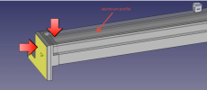
The aluminium profile is first inserted into the holder groove indicated by arrow 3. As you can see, this groove follows the contour of the aluminium profile, ensuring a secure fit. Then, the profile is freely inserted into the groove shown by arrow 2 (refer to the photo above).
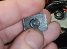
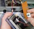
A strip of tape can be applied to this location, indicated by the large arrows. My profile fits very tightly, but tape will help ensure better fixation.
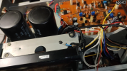
Here’s how it looks when everything’s put together. When I was filming a video, the camera kept getting overexposed, so I just stuck a bit of electrical tape on the front — I’ll take it off later.
Unfortunately, I can’t add any more photos right now — there’s a limit on how many I can include here. But don’t worry, I’ll be back with the rest of the story and more images in a little while!
I wonder how correct the translation is, is everything clear in the text?
I’d like to share how I made LED backlighting for the Sansui BA‑F1.
Please accept my apologies for the translation — I don’t speak English well.
I made new backlighting for the needle and peak indicators, as well as for the amplifier power button.
My goal was to:
make the indicators’ backlighting yellow, like in the original;
increase the brightness of the backlighting;
add a red backlight for the alarm mode.
I ran many experiments with backlighting colours and came to the conclusion that yellow is the most informative colour. With green and blue, the power scale and the red peak indicator are hard to see. Besides, these colours look unnatural — in my opinion, they’re rather ugly.
I have two such amplifiers: my custom backlighting is installed on the top one, while the bottom one has the stock version.
As you can see in the comparison, the top option is more informative — the needles, power scale, and peak overload indication are much easier to see.
I also added red indicator backlighting that activates when the amplifier is powered on and when the amplifier’s protection circuit is triggered.
The new backlighting was implemented using a three‑colour (RGB) LED strip. I obtained the desired yellow colour by simultaneously activating the red and green diodes on the strip.
I designed and 3D‑printed the backlight holders.
I installed the holders right where the original backlighting was — there are mounting points for that, marked with arrow 1.
An aluminium profile fitted with a matte light diffuser (Feron cab 262) is also used. Inside the profile, two LED strip segments are securely attached with adhesive.
The aluminium profile is first inserted into the holder groove indicated by arrow 3. As you can see, this groove follows the contour of the aluminium profile, ensuring a secure fit. Then, the profile is freely inserted into the groove shown by arrow 2 (refer to the photo above).
A strip of tape can be applied to this location, indicated by the large arrows. My profile fits very tightly, but tape will help ensure better fixation.
Here’s how it looks when everything’s put together. When I was filming a video, the camera kept getting overexposed, so I just stuck a bit of electrical tape on the front — I’ll take it off later.
Unfortunately, I can’t add any more photos right now — there’s a limit on how many I can include here. But don’t worry, I’ll be back with the rest of the story and more images in a little while!
I wonder how correct the translation is, is everything clear in the text?