• The move to the new server is done. There are some software and database maintenance updates in process. This has us passing the hat around to help out. We appreciate any donations. Seriously, even a dollar helps. The payment page may be found here - https://www.audiokarma.org/support.html

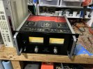
Sansui ba-5000 bias adjustment showing..0mA

xalara76

Active Member
Does anyone have an image of where to put DMM leads ? Looking at factory service manual and following what’s written gives me weird results, 0mA. The amp sounds incredible when playing, and does get a bit warm.. just unfamiliar with how warm is too warm. The fan does NOT come on so this all may just be normal.

Positive lead on red wire from transformer, and black lead on the pin from board right below it per channel.

What am I doing wrong ? Both channels show an equal 0mA, it’s from my understanding this is to be set to 180Ma .. please help. Thanks
 
Register to hide this ad
And remove the fuse for the channel you are measuring. this is wrong.:mad:
 
Last edited:
Ma as in amps? Are you sure the bias spec isnt in Mv, volts?

And just an FYI, there is a specific Sansui subsection here, probably get some more help there.
 
The Sansui SM procedure for setting bias on those is retarded. Pick an emitter resistor, not one of the drivers, and set the bias for about 30mA through it, about 10mV drop across it.
ETA: if it works well and sounds good, you probably shouldn't screw with it. Those amps do run a little warm.
 
Last edited:
There is another way that is quite easy and was used on McIntosh units over the years. Just use the main line draw. Turn the pots down all the way. Turn the unit on and wait 30 minutes. Adjust one channel (side) at a time. Watch the mainline draw and increase 150 mA per channel. Once notch distortion minimizes there is no benefit in increasing bias current. You could also do it with a distortion analyzer.
 
I seem to remember the main transformer being about 130 deg on a dialed in BA-5000.
 
Just seeing this now - Thanks for all the replies guys. So to be sure - I’m going to remove the wire from F-2516 (that’s circled in red in picture )
and attach positive lead from DMM

then place alligator clips on negative terminal below (still attached)

If I put it around 130-150mA would that be beneficial at all as suggested by some instead of the factory rated 180mA ?
Did you disconnect the wires from F-2516 and put your meter in series?

Craig

?
I seem to remember the main transformer being about 130 deg on a dialed in BA-5000.
Btw, notch distortion minimized at just below 150mA mainline draw
View attachment 3457256
The Sansui SM procedure for setting bias on those is retarded. Pick an emitter resistor, not one of the drivers, and set the bias for about 30mA across it.
ETA: if it works well and sounds good, you probably shouldn't screw with it. Those amps do run a little warm.
Also is your multimeter leads in the correct terminals for current reading?
Did you disconnect the wires from F-2516 and put your meter in series?

Craig
 
Just seeing this now - Thanks for all the replies guys. So to be sure - I’m going to remove the wire from F-2516 (that’s circled in red in picture )
and attach positive lead from DMM

then place alligator clips on negative terminal below (still attached)

If I put it around 130-150mA would that be beneficial at all as suggested by some instead of the factory rated 180mA ?


?
No. Just hook your meter, on DC volts or millivolts, across one emitter resistor and do the math. V/R=I. 10mV will give you just about 30mA. There are four sets in parallel, plus the drivers. Parallel currents are additive. IMO, the exact bias really isn't crucial, so long as it's in the 150-180mA range.

I really dislike the method in the SM of removing the +B wire and putting an ammeter in series. It's a disaster waiting to happen.
 
I like tarior's recommendation too. I've used V=IR to measure across a emitter resistor on other Sansui gear (2000a and 5000a comes to mind. even the 9090 says to pull a Vcc fuse and measure the current).

I'd measure across one of the emitter resistors and see where it is. set the bias to 10mV-12mV across one of the 0.33R emitters. My guess this will be close enough.

Here is the service manual bit showing the bias procedure. Yikes! Mini-grabbers are a must.

1742400159779.png
 
The Sansui SM procedure for setting bias on those is retarded. Pick an emitter resistor, not one of the drivers, and set the bias for about 30mA across it.
ETA: if it works well and sounds good, you probably shouldn't screw with it. Those amps do run a little warm.
I suspect you mean mv and not ma.
 
Back
Top Bottom