• The move to the new server is done. There are some software and database maintenance updates in process. This has us passing the hat around to help out. We appreciate any donations. Seriously, even a dollar helps. The payment page may be found here - https://www.audiokarma.org/support.html

Sansui D90 Repair - Low Output Volume

DavidBowie

New Member
I've got a Sansui D90. I've replaced the belts and when playing a cassette, it plays at very low volumes, although when my amp is turned up to max it is audible. The playback level adjustment potentiometers make little difference. This is my first cassette deck repair so I am unsure of what the potential issues could be.

The board looks good visually, with no bulging capacitors or obvious issues. Could it be an issue with azimuth alignment? I've heard you should not mess with it as you could do more harm than good, especially if that is not the issue.

Thanks for the help!
 
Register to hide this ad
This is my first cassette deck repair so I am unsure of what the potential issues could be.
OK, I've got a couple of questions:
  1. Do you have the Sansui D90 Service Manual? If not, you can download it here: https://elektrotanya.com/sansui_d-90_sm.pdf/download.html#dl
  2. What test equipment do you have to troubleshoot?
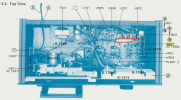
The first thing to do is to clean the long sliding PLAY/REC switch with Deoxit D5 (see diagram below). Try to spray it into the holes in the long switch, then work the switch back & forth about 40 times.

1738645820061.png

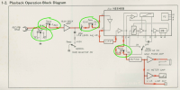
Here is the simplified schematic of the circuit in Play.
You can trace the signal path from the PB Head through the switch, Playback Amp, another switch, through the chip, through another switch and to the Line Out and VU meter.
All of the circled switches are part of that long switch shown above. If any do not make good contact, the playback signal will not get through to the output
These long switches are notorious for getting oxidized contacts and need to be cleaned to make contact again.
The REC pushbutton should move this switch to the REC position when you press it down and back to PLAY when released.

After spraying Deoxit on the switch and working it many times, let it sit overnight to dry. Don't over-spray it else you will drip cleaner all over your board.
Try this and let me know if it helps.

1738645945687.png
 
Hi, thanks for the response!

1. I do have the Sansui service manual, I should've mentioned that in my original post.
2. I have both an analog and digital oscilloscope, a basic multimeter, an audio signal generator, and a component tester.

I have sprayed the switch and worked it back and forth. Unfortunately, I don't hear a noticeable difference; however, I am unsure if I was able to sufficiently get the contact cleaner to the contacts inside of the switch. If there is an easy way to test, I'd be happy to try or I can desolder the switch from the board and test it out of circuit and possibly disassemble and clean it that way.

The audio sounds quite clear and doesn't sound distorted to me. If it is not the switch but instead the amplifier, I've never done in-circuit testing before but I assume a good place to start would be checking the given test points given in the schematic diagram?

1738811247916.png

Thank you for the help.
 

Attachments

  • 1738811225298.png
    1738811225298.png
    283.7 KB · Views: 1
I think the muting circuit is engaged. I'll have to look at the schematic but there are probably 2 muting transistors, one for each channel. They probably get turned on when the unit is in Stop and FF/RW. There may be a broken wire going from a leaf switch in the mechanism to the pcb.
 
I think the muting circuit is engaged. I'll have to look at the schematic but there are probably 2 muting transistors, one for each channel. They probably get turned on when the unit is in Stop and FF/RW. There may be a broken wire going from a leaf switch in the mechanism to the pcb.
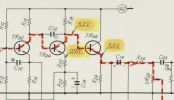
I believe that TR15 and TR16 are the main muting transistors? To test, I shorted the emitter and collector of TR15 and when playing a cassette, the volume on the left channel is much quieter. I believe this suggests that the muting transistors are not to blame unless my test is significantly flawed. I will attempt to verify by checking the base voltage in the different modes tomorrow.

1738822805212.png
 
Last edited:
Here are a couple of simple tests for you to try to isolate the problem:
  1. When you play a pre-recorded tape, do the VM meters move close to 0dB?
  2. If you put in a blank tape and try to record (by pressing REC & PLAY) can you adjust the REC Volume control to adjust the REC volume as seen on the VU meters?
  3. Have you cleaned the tape heads with isopropyl alcohol?
  4. How do you have the cassette deck connected to your amplifier (what make/model amplifier) and what inputs do you have it connected to?
    • You should have LINE OUT (PLAY) of the tape deck connected to TAPE IN of your amp
    • You should have LINE IN (REC) connected to TAPE OUT of your amp.
    • Select the source that you want to record, (e.g. FM, Phono, Aux) and Tape Mon button on the amp out.
 
1. The VU meters do not move at all when playing or recording. Using a 1.5v battery I can get the needles to move so the problem isn’t with the VU meters themselves.

2. When recording a blank tape I can adjust the recording levels however the VU meters do not move once again. On playback of the tape I can hear me changing the recording levels.

3. I have cleaned the tape heads with isopropyl alcohol.

4. I have a Pioneer SX-3500 amplifier and I have the cassette deck’s line out (play) connected to my amplifiers tape play. I then have the line in (rec) of the cassette deck connected to my amplifiers tape rec. I swapped the connections on my amplifier just to see if I did have it wrong and I no longer had any signal at all. Furthermore, earlier I connected the tape out to the aux input on my amplifier to verify that it is not the amplifiers fault.

I also tested the base voltage of TR15 relative to ground and it sat at around 0.6-0.7 volts? I’m not sure what that would mean exactly whether that would have the transistor be partially open or if means nothing.
 
Alright, let's try tracing the audio path in REC mode from the Line In through the Dolby IC.
Here is the schematic diagram:
  1. Use your signal generator to generate a 1kHz sine wave about 70mV and attach it to the Line In RCA jack, L channel.
  2. Put the deck into REC mode (with a blank tape) by pressing both the REC & PLAY buttons.
  3. On the schematic, follow the blue line from the L Line In through VR601a, S601c to pin 5 of IC01 (NE646B Dolby IC).
  4. Use your scope with the ground connected to chassis, set voltage to 5v, AC coupled, and you should see your 1kHz sine wave and be able to follow it through.
  5. The signal does go through VR601a, the REC level control (turn this up if you don't see a signal).
  6. Can you see the sine wave on pin 5 of IC01 on your scope? What is the voltage level?
  7. Coming out of the Dolby chip you should see the signal on pin 3 of IC01.
1738874343094.png
 
Last edited:
1. The VU meters do not move at all when playing or recording. Using a 1.5v battery I can get the needles to move so the problem isn’t with the VU meters themselves.

2. When recording a blank tape I can adjust the recording levels however the VU meters do not move once again. On playback of the tape I can hear me changing the recording levels.

3. I have cleaned the tape heads with isopropyl alcohol.

4. I have a Pioneer SX-3500 amplifier and I have the cassette deck’s line out (play) connected to my amplifiers tape play. I then have the line in (rec) of the cassette deck connected to my amplifiers tape rec. I swapped the connections on my amplifier just to see if I did have it wrong and I no longer had any signal at all. Furthermore, earlier I connected the tape out to the aux input on my amplifier to verify that it is not the amplifiers fault.

I also tested the base voltage of TR15 relative to ground and it sat at around 0.6-0.7 volts? I’m not sure what that would mean exactly whether that would have the transistor be partially open or if means nothing.
Your test shorting the E-C was faulty, That emulates turning the transistor on and shorts the output of the deck.
0.6V at the base means the transistor is turned on, so, yes it is muting.
With muting on you will not read anything on the meters either!
The muting signal goes to TR609 base. If the base is 0V, tr609 is on and the deck will mute. We want TR609 base to be high.
For a quick test REMOVE TR15 and TR16 and you should have output and meters. Be careful, use solder removal braid. If you don't have any, buy some. Tech Spray is a good brand. 0 .1" thick.
 
@dr*audio has a good comment above. And since TR609 drives the base of both TR15 & TR16 AND you have low output signal on both channels, maybe TR609 is bad?
 
Your test shorting the E-C was faulty, That emulates turning the transistor on and shorts the output of the deck.
0.6V at the base means the transistor is turned on, so, yes it is muting.
With muting on you will not read anything on the meters either!
The muting signal goes to TR609 base. If the base is 0V, tr609 is on and the deck will mute. We want TR609 base to be high.
For a quick test REMOVE TR15 and TR16 and you should have output and meters. Be careful, use solder removal braid. If you don't have any, buy some. Tech Spray is a good brand. 0 .1" thick.
You are correct, after removing TR15 and T16, the deck's volume and VU meters came back! Another issue I had previously was with the pause button before removing TR15 & TR16. Before removing them, if the deck were playing, pressing pause would cause the solenoid (SOL701) to fire after about a second, unpausing itself. Now after removing TR15 and TR16, the pause button functions normally?

With TR15 and TR16 removed I am measuring the voltage of TR609's base. At any time other than paused, it sits at 8.7 volts. However when pause is turned on it only drops to 8.6 volts. This behaviour is consistent as well. The pause microswitch S702 is functioning correctly as well I checked it with a multimeter.
 
You are correct, after removing TR15 and T16, the deck's volume and VU meters came back! Another issue I had previously was with the pause button before removing TR15 & TR16. Before removing them, if the deck were playing, pressing pause would cause the solenoid (SOL701) to fire after about a second, unpausing itself. Now after removing TR15 and TR16, the pause button functions normally?

With TR15 and TR16 removed I am measuring the voltage of TR609's base. At any time other than paused, it sits at 8.7 volts. However when pause is turned on it only drops to 8.6 volts. This behaviour is consistent as well. The pause microswitch S702 is functioning correctly as well I checked it with a multimeter.
TR609 is suspect. What is the voltage on the emitter and collector with TR15 and TR16 removed? Check B, E, C in play and stop modes.
 
The collector is 9.4v when playing and stopped and 9.3v when paused.

The emitter is also 9.4v when playing and stopped and 9.3v when paused.

I remeasured the base and still got 8.7v when playing and stopped and 8.6v when paused.
 
It was a switch after all, I traced the base of TR609 through the 2.2k resistor back to S704 and found it wasn't closing fully when playing. I fixed that and the emitter? on TR609 was showing 0v when playing! I soldering back TR15 and TR16 and it works great!
 
Back
Top Bottom