• The move to the new server is done. There are some software and database maintenance updates in process. This has us passing the hat around to help out. We appreciate any donations. Seriously, even a dollar helps. The payment page may be found here - https://www.audiokarma.org/support.html

Sansui G-2000 Keeps Blowing Fuses

BackInThe70s

New Member
I have a Sansui G-2000 that I've owned for approximately three years, which I purchased from a buyer on eBay. The problem I'm having is that one of the fuses keeps blowing now. It is a 4A 12.5 volt fuse located in a bank of three fuses, to the side of the power transformer. It is the right most fuse, to the left of the transformer. This is a problem I experienced almost a couple of years ago, when turning the receiver on, and would lose sound within a few seconds. Someone recommended new fuses which fixed the problem - then. I haven't been using my stereo for over year so recently when I turned it on, I experienced the no sound issue again. Luckily I had extra fuses around so I located the burned out fuse and replaced it. However, as soon as I turned power on the same problem occurred. I ended up replacing the fuse a couple more times, only this time I watched the area of the fuse when I did so. I could visually see the fuse blow within a couple of seconds of turning power on. Obviously I can't keep practicing Einstein's theory of insanity with replacing the fuse with the same ones. Any suggestions on what this problem could be, and how I might address it? Thank you.
 
Register to hide this ad
something is shorted causing the fuse to blow .
you need a minimum of a multi-meter and soldering iron etc and screwdrivers to find what is shorting out .
fuse will be 125v not 12.5v .
 
greetings;
If memory serves me right on the 2000 (batting avg. 250 lol) , I believe some boards need service.. perhaps some modification, too. Perhaps update these boards. You'll need some good skills in de-soldering and board removal. No task for an amateur with a non regulated soldering gun and no experience.
service manual here:
https://www.hifiengine.com/manual_library/sansui/g-2000.shtml
which model is it? Perhaps some searches you can perform using audiokarma model will reveal some prior posts. Don't be shy about posting your skills. It's not a super great unit but not a bad brand model.

Got a dim bulb tester and dmm etc??
 
Well, my electronics repair skills is next to nothing, so I am very limited in what I can do myself. This is the Sansui G-2000, so I'm not sure what is being asked regarding which model is it. I thought that was the model number. I can check and replace fuses, change out old bulbs with new LED ones, that sort of thing, but pulling circuit boards by desoldering and such, I would break something.
 
The G-2000 evidently was sold in a "general" model and in "L" and "SS" models. There are some differences, so that may be the reason for the question. I have a G-4500 so I am a little familiar with the architecture.

Regardless of the type, it would be good to stop installing fuses so that no more damage is done.

Generally, the power supplies are about the same for any UL/CSA type, so if your model is a 120VAC voltage only type (without an input voltage selector) that should clarify any variations in power supplies. If you have a 220/240VAC or multi-voltage unit, we would need to know that.

Presuming it is a 120VAC type, and given that the final output transistors are not plug connected, it would be a good idea to acquire a multimeter with a diode test function and check the main rectifier diodes and output transistors in-circuit. The important checks are to verify that the main rectifiers are not shorted, and that the E-C junctions of all four of the output transistors are not shorted. This can be done without desoldering anything (yet).
 
g'day..
Very hard to decide for someone what to do. The link at hifiengine shows the 2000L &2000ss both similar. There is no harm in taking covers off and compare the service manual to your look-over. I'm not implying working on it just get familiar and decide as depending where you live.. Eboy prices are couple 100 working.. so perhaps a trade if cosmetics look good for a another working receiver. Don't know where you live but still an option locally.

taking a quick look at the service manual.. if FM was working don't touch it that's separate from the main board.,, voltage selector board leave that perhaps, looks like the main board has the power supply and mains caps on that.. don't need to remove that but the front face assembly may need to come or just moved out of way to get at the tone control section?

You have to be able to read the schematic. location of parts and testing transistors, diodes, resistors. You'll need a DMM, build a dim bulb tester (DBT).

post pics... if you like.
bink
 
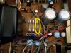
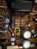
Attached is an image of the inside of the receiver, and I've highlighted the specific fuse that keeps blowing.
 

Attachments

  • Sansui G-2000 Stereo Receiver.jpg
    Sansui G-2000 Stereo Receiver.jpg
    85.1 KB · Views: 76
the pix doesn't do it - you need to post the schematic, as large as you can make it by cropping,
then identifying the fuse on the schematic. your pix is fuzzy but I'm assuming there's stenciling
on the board.

once this fuse is ID'd, we can look at what it's powering. the fuse may be incorrect for values
based on whoever did the first replacement and it happened to have worked for you
in the past.
 
the pix doesn't do it - you need to post the schematic, as large as you can make it by cropping,
then identifying the fuse on the schematic. your pix is fuzzy but I'm assuming there's stenciling
on the board.

once this fuse is ID'd, we can look at what it's powering. the fuse may be incorrect for values
based on whoever did the first replacement and it happened to have worked for you
in the past.
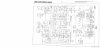
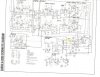
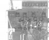
I have scanned the schematic diagram, two files spilit in half, left and right, and one combined.
 

Attachments

  • Sansui G-2000 Stereo Receiver_Schematic_Left Side.jpg
    Sansui G-2000 Stereo Receiver_Schematic_Left Side.jpg
    69.1 KB · Views: 6
  • Sansui G-2000 Stereo Receiver_Schematic_Right Side.jpg
    Sansui G-2000 Stereo Receiver_Schematic_Right Side.jpg
    65.5 KB · Views: 5
  • Sansui G-2000 Stereo Receiver_Schematic_Combined.jpg
    Sansui G-2000 Stereo Receiver_Schematic_Combined.jpg
    56.6 KB · Views: 6
Bob??? I use a snippet tool... easy as pie in a seconds off the pdf.. :D
OP... get your magnifier out and look at the fuse lettering. I.D. from the snippet which one.
bink


upload_2019-2-24_10-31-55.png
 
Bob??? I use a snippet tool... easy as pie in a seconds off the pdf.. :D
OP... get your magnifier out and look at the fuse lettering. I.D. from the snippet which one.
bink


View attachment 1430547
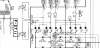
Okay, I think I've identified the fuse that keeps blowing, on the schematic diagram. Hate to keep asking stupid (to you/this group) questions, but I do not have any work bench experience with electronics technology troubleshooting and repair. What is the next step?
 

Attachments

  • Sansui G-2000 Stereo Receiver_Schematic_Left Side_Fuse Identified.jpg
    Sansui G-2000 Stereo Receiver_Schematic_Left Side_Fuse Identified.jpg
    108.5 KB · Views: 4
Attached is an image of the inside of the receiver, and I've highlighted the specific fuse that keeps blowing.

index.php


As suspected, it appears to be the fuse adjacent to terminal 11 in the 5-pin power connector, and the UL/CSA unit would require a 4A fuse in that position. Those items previously mentioned should be tested for shorts.
 
...Hate to keep asking stupid (to you/this group) questions, but I do not have any work bench experience with electronics technology troubleshooting and repair. What is the next step?

The "stupid question" would be the one that someone was afraid to ask. We ALL started at ground zero in electronics. You're doing the right thing. Fortunately, I believe you'll find that AK is all audio, no attitude.

First, do you have access to a multimeter? This will be critical. It would be best if you could borrow/beg/steal/buy (well, maybe not steal) a meter with a diode check function, identified by a symbol like this: -►|-
Even some of the most economical meters have this. A meter with a plain resistance scale would work, but the diode check range gives us a lot more information.

With no power connected, the diodes adjacent to the fuses should be tested for shorts. Any resistance below a few ohms would constitute a short.

The two large gray filter capacitors (4700µF/35V) in the photo should also be tested for shorts. The initial resistance may be low, but after a few seconds the resistance reading should begin to climb, yielding the correct measurement.

In either case, if a short is detected, it may be the device being tested or something connected in the circuit with it, but these measurements will help point us in a direction.

The same should be done with the four power output transistors, a pair of 2SD313 and another pair of 2SB507. They are mounted to the heat sink to the rear of the unit on the left side. The lead assignments for each of these transistors, from left to right, is Base - Collector - Emitter (B-C-E). You will want to test the two right leads, collector and emitter, for resistance in both directions. We will need to see the results of the measurements, so make a note.
 
First, do you have access to a multimeter?

Yes, my wife is making a run at Walmart and I've asked her to pick a specific one up with a diode setting.

With no power connected, the diodes adjacent to the fuses should be tested for shorts. Any resistance below a few ohms would constitute a short.

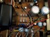
Do you mean these that I have circled in yellow? Please understand that you are giving instructions which are equivalent to providing navigation instructions on an old road map, which must be explicit.

The two large gray filter capacitors (4700µF/35V) in the photo should also be tested for shorts. The initial resistance may be low, but after a few seconds the resistance reading should begin to climb, yielding the correct measurement.

Do I simply place the red and black test leads at the top of them?

In either case, if a short is detected, it may be the device being tested or something connected in the circuit with it, but these measurements will help point us in a direction.

What am I looking for? I've fumbled my way around the circuit board and I do obtain numerical readings, but as a novice I can't assign meaning to them.
 

Attachments

  • Sansui G-2000 Stereo Receiver_diodes.jpg
    Sansui G-2000 Stereo Receiver_diodes.jpg
    55.6 KB · Views: 5
pix still fuzzy but I'll assume your facts are correct. first pull fuse, one probe on
left side of that fuse, and the other side on the two (at different times)
measure the resistances. if not zero then transformer is OK.

then switch meter to AC. use same technique to measure AC volts across the full
secondary then each section. both sections should total the full AC across the secondary,

do NOT simply touch the terminals, use a probe clip, or an alligator. ONE SLIP = DESTRUCTION.

these tests will show what the AC voltages are since the fuse you described is low voltage.
this will also show (using more of the schematic) what this power feeds - the next stage
and whatever that does.

IOW follow the suggestions above. (I would need more and better scans - my eyes shake,
and my hands are fuzzy)
 
After Bob's above described voltage test with the secondary fuses removed, check everything marked with an arrow - POWER OFF:

SansuiG-2000PSBoard.jpg [/IMG]
 
After testing those diodes for shorts/opens, and the capacitors for shorts, we can move to the output transistors. Since you have a camera and the unit in question, a better photo of the area rearward from the transformer would be helpful.

This is the general area in question:

SansuiG-2000Outputs.jpg
 
After Bob's above described voltage test with the secondary fuses removed, check everything marked with an arrow - POWER OFF:

View attachment 1430918 [/IMG]
Can you please explain explicitly how I check for readings? For example, for the diodes I assume I touch either ends, but does it matter red and black on any particular side? And after doing so, what readings am I looking for? As for the gray capacitors how do I test those, meaning where do I place the probes?
And when you say with secondary fuses removed, can you elaborate on that? Do you mean in that bank of three fuses, remove all of them?

Update: I noticed that my phonograph was plugged into the back of the receiver. I unplugged it, popped in another fuse and turned the unit one. It DID remain on a bit longer, but still burned out the fuse. Back to the drawing board.
 
First and foremost, stop installing fuses and powering the unit on. We are trying to reduce damage, and every surge of power has a good chance of creating more problems.

It appears that Walmart has several $8-10 meters with a diode test function AND other useful ranges. The 830 models they show online are based upon the Mastech 830, which should be fairly capable.

When you get your meter in hand, apply a layer of tape around the exposed metal probes to all but the very end of the tip to prevent inadvertent shorting when testing. This is important, and even the most seasoned veterans slip (which is why we use the "probe condom" approach).

For performing Bob's test, remove both of those 4A fuses and the adjacent 1A fuse and set them aside. Power the unit on, set your meter to measure AC voltage, connect the black probe to a good chassis ground (probably any metal area) and CAREFULLY touch the red probe to each of the purple wires (one at a time) and then to each of the blue wires. You should be able to back-probe the circuit board connector without removing it. Make a note of the voltage at every test point.
 
Don't power this unit on... you can test cold as described.. get a dmm.. you can get a cheap one for sometimes less than 20$. home depo etc.. Also... Look on the sides of the large mains capacitors (middle pic) and report what you read.
 
Back
Top Bottom