
• The move to the new server is done. There are some software and database maintenance updates in process. This has us passing the hat around to help out. We appreciate any donations. Seriously, even a dollar helps. The payment page may be found here - https://www.audiokarma.org/support.html

Sansui G-7500 Assistance Needed

zelgy1

Member
Hi all! I've started my new project, troubleshooting a Sansui G-7500. I've read many a post on this unit and looks like I'm in for a good one, but I'm ready for the challenge. The relay is NOT clicking/activating, so of course no sound output. Unit does power up and all fuses have been checked ok. No visual damage to components from what I can tell. I've begun by checking voltages at a number of points on the Power Supply Board F-2980, with readings noted below. Please note I'm no pro, but I know enough to be deadly. Below is what I have found so far. Based on my findings, I suspect I have a transistor or 2 that have failed. However, I'm a bit miffed as no fuses have blown. I've read that you DO NOT want to start throwing parts at this unit as it can open up a can of worms. That being said, I kindly ask the professionals on this site for the next step. If a reading doesn't make sense, please let me know and I'll retest.

Checked voltage at resistors R81 and R82.
R81: 59.5 VDC
R82: 2 VDC

IC 01 (pins numbered from the front to back)
1: 48.2 VDC
2: 0 VDC
3: .7 VDC
4: 0 VDC
5: -3.6 VDC
6: 93.8 mVDC
7: 7.8 VDC
8: 47 mVDC


Test point readings: (if I didn't list a particular test point, it signifies the reading was correct)
4&5: 7.5 VAC
6&8: 41.6 VAC
9: 53.0 VDC
10: 51.7 VDC
13&15: 45 VAC
17: -59.5 VDC
18: 59.6 VDC
30: 12 VDC
50: -54 VDC
51&53: 59.3 VDC
52&54: 59.5 VDC
55&57: 59.3 VDC
56: 2.5 VDC
58&60: 2.0 VDC
59&61: -59.4 VDC
64&66: -59.3 VDC
63: -59.4 VDC
65: 0 VDC
 
Last edited:
Register to hide this ad
I think you need to revisit your voltage readings, they actually make little sense at all.
Most of them will be DC voltage, not AC.

There wont be anything to read at the speaker outputs without the relay engaged, you have to measure the offset pre-relay.

Once you get your readings in order we might be able to make some sense of whats going on.
 
I think you need to revisit your voltage readings, they actually make little sense at all.
Most of them will be DC voltage, not AC.

There wont be anything to read at the speaker outputs without the relay engaged, you have to measure the offset pre-relay.

Once you get your readings in order we might be able to make some sense of whats going on.

Now that I have my head pulled out of my arse, let's give this another try. I have updated all my readings in the original post. As far as measuring the offset pre-relay, if you can point me in the right direction it would be greatly appreciated.
 
You can measure the DC voltages at pins 43 and 45 on the F-2980 power supply/main amp board.

It seems the 0.7V measured at pin 3 of the protection IC is a red flag.

Moreover, the ±59V at all of the output transistor connections is another indicator of shorted outputs.
 
Last edited:
You can measure the DC voltages at pins 43 and 45 on the F-2980 power supply/main amp board.

It seems the 0.7V measured at pin 3 of the protection IC is a red flag.

Moreover, the ±59V at all of the output transistor connections is another indicator of shorted outputs.
I measured 59.9 VDC @ pin 43 and 1.9 VDC @ 45.
 
Some NJW0302G and NJW0281G devices might be in your future, along with various other supporting actors.

There should be only a few millivolts present there. Follow the circuit back to the main outputs and the problem may become obvious. To verify, turn off power and perform the 6-way diode test of the output devices. I'm guessing you'll find some dead shorts.

https://www.audiokarma.org/forums/i...lar-junction-transistor-testing-basics.43186/
 
Some NJW0302G and NJW0281G devices might be in your future, along with various other supporting actors.

There should be only a few millivolts present there. Follow the circuit back to the main outputs and the problem may become obvious. To verify, turn off power and perform the 6-way diode test of the output devices. I'm guessing you'll find some dead shorts.

https://www.audiokarma.org/forums/i...lar-junction-transistor-testing-basics.43186/
I'm embarrassed to even ask, but I assume the output transistors are the TR601 and TR602's? I'm guessing the best way to test is removed from the circuit completely? I want to ensure I'm testing all the appropriate transistors and any other components to avoid chasing my tail. I certainly appreciate the helpful tips and patience as I work through this.
 
I'm also reading on a few posts that the trimmers should be replaced. If this is advised, can someone please offer a PN? I purchase most of my parts from Mouser here in the States.
 
TR601/602 are the outputs on the F-2981 boards - Two of each device.

If would also be prudent to test the driver transistors for those pairs (TR16-TR19) as well as the emitter resistors, R71, 72, 77, and 78. Depending upon your results, there may be more testing before putting together that parts order.

These devices can probably be tested in-circuit, since a short-circuit will be evident regardless of surrounding devices.
 
TR601/602 are the outputs on the F-2981 boards - Two of each device.

If would also be prudent to test the driver transistors for those pairs (TR16-TR19) as well as the emitter resistors, R71, 72, 77, and 78. Depending upon your results, there may be more testing before putting together that parts order.
Excellent, thanks so much! Assume these should be removed from the board to test?
 
So I've confirmed shorts in a couple output transistors. I will continue to test other components this evening. Is there an easy disassembly process to get at the output transistors without de-soldering a bunch of leads to remove the back panel? Seems like I may be missing something. Appreciate the continued assistance!
 
;)Just for grins- Have you checked all your fusible resistors? Those blue/grey bad boys -
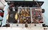
You don't happen to have the component locations readily available do you? I've read conflicting posts on which of the resistors are the fusible type.
 
There the blueish ones that are in the pic .. elevated from touching the Circuit board .. 220 , 68 ohms I believe and a few others .. you can measure them "in circuit"
 
Those Bluish resistors are not fusible. They are NIR, which are "flameproof" resistors.
I wondered about that. Thanks for clarifying! As I’ve confirmed a couple output transistors are indeed shorted, directions on getting to the output transistors easily would be appreciated.
 
Update on component checks. The following transistors were removed from the circuit and tested good (TR09, TR10, TR15-TR20). The emitter resistors were removed and found R77 was bad. Please note the following output transistors were tested while in the circuit as I have yet to determine how to properly remove them from the back panel. I have confirmed left channel output resistors TR601 and TR602 are both bad. I tested the right channel output resistors and found the following: TR601 with + probe on base and - probe on collector, voltage climbs but all other tests pass. TR602 with + probe on collector and - probe on base, voltage climbs but all other tests pass. I suspect this is due to a capacitor being in the circuit. I plan to replace these either way. If there are any other checks that should be made, please let me know before I start ordering/replacing parts. As always, thanks much for feedback!
 
Hi all! I was able to get at the output transistors, removed, and confirmed the left channel outputs are both shorted. I have ordered replacement output transistors for both channels, emitter resistors, and trim pots. I'll keep everyone posted on how everything turns out.
 
Back
Top Bottom