

Hello!!!
I am restoring a Sansui G-9000 that had a serious heating problem on one channel.
I did a thorough restoration based on other restorations published in AK.
After many twists and turns on the right channel, I cannot get the BIAS current below 20mV. (manual say 16mV)
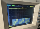
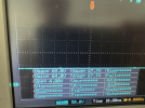
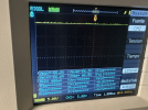
And I could see that when the voltage ripple entering the F-2806 board on the external leg of resistors R23 and R24 is high (1.2 or more mV), the BIAS goes up to approximately 100mV.
But if the ripple stays at 600mV, the BIAS stays at 20mV.
That led me to think that there was a problem with the rectification (diodes or capacitors) on the power supply boards.
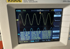
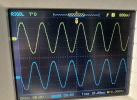
I measured the voltage at the transformer output and the waveform is clean and smooth.
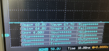
After the SS-5 and SS-5R diodes it is not as nice as I imagined. And after the large capacitors (which are new Nichicom) there is a ripple of 600mV.
It seems too much ripple for this power supply.
Can anyone give me some opinion? Or have you seen this? What is the correct ripple for this equipment?
I am attaching some photos that show everything I said above.
Thank you in advance.
I am restoring a Sansui G-9000 that had a serious heating problem on one channel.
I did a thorough restoration based on other restorations published in AK.
After many twists and turns on the right channel, I cannot get the BIAS current below 20mV. (manual say 16mV)
And I could see that when the voltage ripple entering the F-2806 board on the external leg of resistors R23 and R24 is high (1.2 or more mV), the BIAS goes up to approximately 100mV.
But if the ripple stays at 600mV, the BIAS stays at 20mV.
That led me to think that there was a problem with the rectification (diodes or capacitors) on the power supply boards.
I measured the voltage at the transformer output and the waveform is clean and smooth.
After the SS-5 and SS-5R diodes it is not as nice as I imagined. And after the large capacitors (which are new Nichicom) there is a ripple of 600mV.
It seems too much ripple for this power supply.
Can anyone give me some opinion? Or have you seen this? What is the correct ripple for this equipment?
I am attaching some photos that show everything I said above.
Thank you in advance.
Attachments
-
 Captura de pantalla 2025-02-19 a la(s) 11.46.38.png900.6 KB · Views: 8
 -
 Captura de pantalla 2025-02-19 a la(s) 11.47.14.png995.1 KB · Views: 8
 -
 Captura de pantalla 2025-02-19 a la(s) 11.47.30.png999.8 KB · Views: 8
 -
 Captura de pantalla 2025-02-19 a la(s) 11.47.47.png956.8 KB · Views: 8
 -
 Captura de pantalla 2025-02-19 a la(s) 11.48.34.png929.1 KB · Views: 8
 -
 Captura de pantalla 2025-02-19 a la(s) 11.48.53.png964.1 KB · Views: 8
 -
 Captura de pantalla 2025-02-19 a la(s) 13.23.54.png718.7 KB · Views: 7
 -
 Captura de pantalla 2025-02-19 a la(s) 13.23.09.png951.7 KB · Views: 8

