• The move to the new server is done. There are some software and database maintenance updates in process. This has us passing the hat around to help out. We appreciate any donations. Seriously, even a dollar helps. The payment page may be found here - https://www.audiokarma.org/support.html

Sansui G-9000 - Yet another 'Protector won't come off' thread

djbono

Active Member
2nd owner, had it for the last 20 years; previous owner also nursed it (friend's dad, so I've known this unit my whole life. In fact this unit knows probably more about me than myself)
Over the last 3 years it
- started to go on Protector while using
- then simply wouldn't come off Protector when trying to launch

I realised that one of my F2806 boards wouldn't "keep" its DC bias value setting, it would greatly swing.
But I did the unthinkable ... I misaligned the left side board by one pin when inserting it back in ... and magic smoke came up from the left F2806.

Instead of debugging, I grabbed two fresh F2806 bare boards designed by Hipocrates, I believe sold by EastPoint (I can't thank the universe enough for their existence) and soldered on.

The boards seem ok; I swapped each of them with the previously known good F2806 board (the one I didn't fry) and I swapped their positions in the unit - exact same results each time; so I conclude tha tmy boards are at least at par with the original one.

The problem right now:
It will go off Protector but ONLY when plugged in through a dim bulb.
It will go off Protector ONLY if I crank the right side DC Bias upwards of 50mV (I Swapped the boards from left to right, and it behaves the same - meaning the F2806 board is probably not at play, but rather the right side power supply ?)

No matter what I try (and I don't usually try much, or for extended periods for fear of breaking stuff) WITHOUT the Dim Bulb - no values of DC Bias on either side will make the Protector disappear. (I didn't try extreme values, but 16mV or 30, or 80mV... on either side or both at the same time... nothing happens.)
I also "feel" like the LEDs are much less powerful than they used to (with or without Dim bulb) -- I know its subjective but if my memory serves me right, the LEDs used to be me retina scorching powerful.

---
I haven't gone through the motions of re-capping any of it;
---
When plugged in with Dim Bulb and protector off - it plays wonderfully, both through the Pre-amp or direct to the power amp. But I don't play it for extended periods of time since I assume its not operating within specs.
----

My question is... what would be your next troubleshooting steps ? I don't feel like swapping caps for sake of it, but I'll gladly do so for the bad ones. My issue is I don't have a tester that can test in situ, so that means desoldering them or 'observing' for obvious leaks and stuff.

I'll take a look at F2808 and 2807 tonight, but I don't feel courageous enough to attack 2809 just yet (unless instructed otherwise here)

Thanks in advance
 
Register to hide this ad
I believe the soft start resistor is R04 3.9ohm 15W large ceramic resistor on the F-2808 board. The soft start relay is the on mounted just below the main P/S board F-2809 AF Power Supply Protector board (when sitting on its back feet).

There are 3 types of protection that could keep the Relays from opening. DC on the outputs, High Current and Thermal Overheating. They are all monitored on the F-2809. Since you do get power up, I am guessing the Soft Start Relay is functioning. That is the first "click" you should hear when powering up. After that comes the RL03 (Reed Relay/Headphone) and RL01/RL02 Speaker Protection Relays. The Reed Relay is up on the Pre-In / Amp Out board on the side.

Sounds like you are able to set your Drivers Bias current voltages to 16mV on full power. Can you also get Drivers (F-2806) DC Offset to zero with no input signal?
 
Thanks for the info !
Ok yes that resistor (and the 2.5A 250v fuse) I had changed several years ago ... due to some "Mishandling" of my part (I did a false move while trying to take a measurement). It worked fine after that for a good while

And yes - they are set (and seem to maintain) near 0vdc on the output speakers - that is when I it goes off protection since I measure it at the spk terminals. I will try and find where to measure it _before_ the spk switch & relay
--
So I'll rule out the soft start resistor
 
If the amplifiers are working properly you need to troubleshoot the protection circuits It sounds like we can rule out the DC offset as a direct cause.
That leaves you the other possible causes of over current and over temp.

If it is not a direct cause then something in the protection circuit itself has has gone out of tolerance, changed or failed.
 
Thanks for this -
Q: SHould I also rule out 'Over temp' since the amp is always cold when I try to turn it on ? (And ... if I do listen to it while plugged in the DBT, it plays quite fine for as long as I'm willing to let it go. Granted I don't overplay it so it doesn't heat up that much)

I'll look into the 2809/Protection circuit then, rather than the L/R pwr supplies

Thanks for steering me in the right direction !
 
Thanks for this -
Q: SHould I also rule out 'Over temp' since the amp is always cold when I try to turn it on ? (And ... if I do listen to it while plugged in the DBT, it plays quite fine for as long as I'm willing to let it go. Granted I don't overplay it so it doesn't heat up that much)

I'll look into the 2809/Protection circuit then, rather than the L/R pwr supplies

Thanks for steering me in the right direction !
No guarantees it is the right direction. BTW don't play it on the DBT for very long and certainly not at any normal volume levels.

If the DBT voltage starves something you may cause some unintended damage.

Have you set the bias and offset to the correct values while not on the DBT? I know you said it won't come out of protection so you have to measure the offset before the protection relay. Do you know where to check offset if the protection relay is not closed?

If it were me I would set the bias and offset to spec while it is NOT on the DBT. That should give us what is hopefully a good baseline to trouble shoot from.

Yes you can likely rule out the over temp.
 
Have you set the bias and offset to the correct values while not on the DBT?
Only the Bias.... I never thought of checking for the DC Offset, since, well, shamefully - no, I do not know where to check :(
Damn, I should have thought about this before !

are there safe tapping points I should look for ? I assume somewhere just before the speaker relays ?
Where is the best/safest way to check ?

THANKS!
 
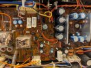
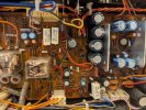
Also - while I was looking for potential tapping points for DC Offset measurement "in situ" ... I realized there's some black goo underneath C17/18/19/20

I attached a picture, does this seem like glue or should I order some capacitors ?
 

Attachments

  • PXL_20251016_205434564.NIGHT.jpg
    PXL_20251016_205434564.NIGHT.jpg
    167.5 KB · Views: 12
Similar goo is seen under C04/C0? (Just next to it, similar cap) - but not under others. But the others are all smaller so might not have required glue ? (If this is glue?)
 
Yes they will be before the relay.
Also - while I was looking for potential tapping points for DC Offset measurement "in situ" ... I realized there's some black goo underneath C17/18/19/20

I attached a picture, does this seem like glue or should I order some capacitors ?
That appears to be Sansui Glue. I don't know for sure if at some point Sansui stopped using the glue that becomes corrosive.

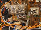
I can point you to the place to check offset. The picture you posted almost shows the area, can you get a little wider shot of what is the lower left corner of the image you posted.

We need to see more of what is to the left of the relay and the relay itself.
 
Thanks !
Don't laugh (at my stupidity) but... where should I put both of my meter's leads ? R and ... ? and L and .. ?
 
Black lead on chassis and red lead on the test point, adjust the appropriate driver offset controls.
 
Check for 24V at the Cathode of the 2nd (lower) Zener Diode. Should have about 24V here for operating the Relays. Just to right of Relay RL03.

PXL_20251016_205434564.NIGHT.jpg
 
Allright,
I managed to find some time to work on it -

I plugged it directly to the mains; let it sit for a few mins and adjusted the Bias at 16.x mV - tends to drift below in time
And then measured the voltage at the points mentioned

@jd3rdcoast - When plugged in WITHOUT the Dim Bulb tester - I measure 23.38Vdc at that point; might have been my unsteady hands or but I saw it moved twice for a few seconds below 22V. But for 99% of the time I measured it was 23.37...23.38V

@mrk229 so I carefully soldered two long wires (and like gauge 18) and did the following measurements, WITHOUT dim bulb

Values vary ALOT depending if I'm setting the Preamp switch - so I provided two measurement sets, one when setting 0.0mV when the pre amp is connected; and one when its disconencted and power amp is capacitor coupled

Note that when the pre-amp is connected, the measurement of the offset "sometime" swings alot in both directions. I don't know if my test wires act as antenneas or whatever.


preamp settingright chleft ch
Pre amp connectedadjusted at 0 mvadjusted at 0mv
sep/direct20.1 mV measured12.2 mV measured
sep/Cap coupled23.5 mV measured11.8 mV measured


preamp settingricht chleft ch
Pre amp connected-15.5mV measured -13.7mV measured
sep/direct-0.8mV measured-1.6mV measured
sep/Cap coupledadjusted to 0.0mVadjusted to 0.0mV

I'll admit I'm extremely confused by this.
 
Oh and while all these tests happened, it never came off protection,.
Still is blinking after a good 30 mins
 
Allright,
I managed to find some time to work on it -

I plugged it directly to the mains; let it sit for a few mins and adjusted the Bias at 16.x mV - tends to drift below in time
And then measured the voltage at the points mentioned

@jd3rdcoast - When plugged in WITHOUT the Dim Bulb tester - I measure 23.38Vdc at that point; might have been my unsteady hands or but I saw it moved twice for a few seconds below 22V. But for 99% of the time I measured it was 23.37...23.38V

@mrk229 so I carefully soldered two long wires (and like gauge 18) and did the following measurements, WITHOUT dim bulb

Values vary ALOT depending if I'm setting the Preamp switch - so I provided two measurement sets, one when setting 0.0mV when the pre amp is connected; and one when its disconencted and power amp is capacitor coupled

Note that when the pre-amp is connected, the measurement of the offset "sometime" swings alot in both directions. I don't know if my test wires act as antenneas or whatever.


preamp settingright chleft ch
Pre amp connectedadjusted at 0 mvadjusted at 0mv
sep/direct20.1 mV measured12.2 mV measured
sep/Cap coupled23.5 mV measured11.8 mV measured


preamp settingricht chleft ch
Pre amp connected-15.5mV measured-13.7mV measured
sep/direct-0.8mV measured-1.6mV measured
sep/Cap coupledadjusted to 0.0mVadjusted to 0.0mV

I'll admit I'm extremely confused by this.
I don't see anything problematic there. Offset voltages always wobble around a bit. There is certainly nothing coming out of the amplifiers that should trigger the protection.

I think you are going to have to troubleshoot the protection circuit itself. @jd3rdcoast posted in #17 about checking voltage at a zener diode.
 
Back
Top Bottom