• The move to the new server is done. There are some software and database maintenance updates in process. This has us passing the hat around to help out. We appreciate any donations. Seriously, even a dollar helps. The payment page may be found here - https://www.audiokarma.org/support.html

Sansui G-9700 burnt resistors on F-3073 Board

angelaudio

Super Member
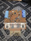
I got this big beast today in non-working condition. Upon powerup the protect light starts blinking and stays that way. So I opened it up and there was no apparent issues up top under the cover, the underside though was a different story. Upon removing the bottom cover I immediately spotted an issue: some burnt components on the F-3073 board
IMG_4795.jpegIMG_4794.jpeg

A Quick Look at the schematic revealed that these burnt components are resistors. I can’t tell if they are all burnt or if it was just one that blew and burnt the other two. According to the schematic these three resistors are R01, R03, and R15 from bottom to top.
IMG_4796.jpeg

What could have caused these resistors to blow? And secondly how can I safely remove the board for maintenance? I removed the 4 screws at each corner but there seems to be another board attached to the opposite side of F-3073 and I cannot remove it.

In addition to the issue on this board I did notice a resistor replaced at F-3072 which may be helping in identifying what failures could have previously occurred. The big gold resistor at the bottom right of the board is the one I’m referring to:

IMG_4793.jpeg
 

Attachments

  • IMG_4797.jpeg
    IMG_4797.jpeg
    90.8 KB · Views: 33
Last edited:
Register to hide this ad
I found another thread where @Hyperion states the following:

“
If you refer to the schematic there are two resistors connected directly to the base of TR01 on F-3073, these are R15 (56Ω) and R03 (1.2KΩ) - by checking what connections are made to the other ends of these resistors you can deduce which is which. The copy of the Service Manual I linked to is not great but it is clear enough to indicate what the values and circuit references are. If you replace R03 with a 1.2KΩ resistor and if for some reason the circuit doesn't work, and providing all other components in this area have been checked, if you need to, you can then request help identifying the resistor value from other G-9700 owners on AK.

Note also that this part of the protection circuitry is the overcurrent detection protection, and if that resistor is burnt, it has had excessive voltage applied to it. It is connected to the output transistors, so suspect some damaged output transistors and components on the power amp board. Also you won't be able to properly test the function of this part of the protection circuit until the rest of the output stage is working correctly.”

With this in mind what would be the next logical step to repair the excess voltage that cooked these resistors? What scenario would have caused excessive voltage to be applied to those resistors? Could it be possible that the amp was pushed too hard or that the outputs were shorted?

Hyperion mentions “If you replace R03 with a 1.2KΩ resistor and if for some reason the circuit doesn't work, and providing all other components in this area have been checked, if you need to, you can then request help identifying the resistor value from other G-9700 owners on AK.” And I’m wondering if I replaced R01, R03, and R15 which other components in this area should I check? And if other components do check out fine, would it then be acceptable to fire up the receiver to check if it works?
 
Last edited:
Hyperion mentions “If you replace R03 with a 1.2KΩ resistor and if for some reason the circuit doesn't work, and providing all other components in this area have been checked, if you need to, you can then request help identifying the resistor value from other G-9700 owners on AK.” And I’m wondering if I replaced R01, R03, and R15 which other components in this area should I check? And if other components do check out fine, would it then be acceptable to fire up the receiver to check if it works?
Replace all the physically damaged components, test all the Output Transistors and all the driver transistors - remove them to do this.
 
I got this big beast today in non-working condition. Upon powerup the protect light starts blinking and stays that way. So I opened it up and there was no apparent issues up top under the cover, the underside though was a different story. Upon removing the bottom cover I immediately spotted an issue: some burnt components on the F-3073 board
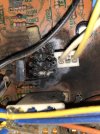
View attachment 3418631View attachment 3418632

A Quick Look at the schematic revealed that these burnt components are resistors. I can’t tell if they are all burnt or if it was just one that blew and burnt the other two. According to the schematic these three resistors are R01, R03, and R15 from bottom to top.
View attachment 3418633

What could have caused these resistors to blow? And secondly how can I safely remove the board for maintenance? I removed the 4 screws at each corner but there seems to be another board attached to the opposite side of F-3073 and I cannot remove it.

In addition to the issue on this board I did notice a resistor replaced at F-3072 which may be helping in identifying what failures could have previously occurred. The big gold resistor at the bottom right of the board is the one I’m referring to:
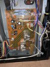
View attachment 3418636
Is that resistor on the F-3072 just hanging by the wires? That is the soft start resistor and has line voltage on it.

g9700r.jpg
 
Is that resistor on the F-3072 just hanging by the wires? That is the soft start resistor and has line voltage on it.

View attachment 3418962
Yup. It was just floating freely that way when I cracked it open. It looked very strange. Would shortening those wires and gluing it to the board be acceptable? Or should I get a new resistor more suitable to this application?
 
Should I pull and check all the transistors on the F-3074 Driver Amp Circuit Board? Are all the transistors on this board considered driver transistors?IMG_4800.jpeg
Do I also check all the transistors on the F-3072 board?

And Lastly check all output transistors on F-3115 and F-3114?

Am I missing any boards?
 
Yup. It was just floating freely that way when I cracked it open. It looked very strange. Would shortening those wires and gluing it to the board be acceptable? Or should I get a new resistor more suitable to this application?
If it's a 3.9 Ohm resistor rated at 15W or more, mount it and then it would be ok.

Should I pull and check all the transistors on the F-3074 Driver Amp Circuit Board? Are all the transistors on this board considered driver transistors?
Do I also check all the transistors on the F-3072 board?

And Lastly check all output transistors on F-3115 and F-3114?

Am I missing any boards?

Don't need to pull. If you pull, you should replace. No, just TR09 and 10 are the drivers....

No.

Yes.

Probably.

Don't trust anything in this unit, if the sofs start resistor was replaced, god knows what else was done.
Look for non-original transistors.
 
Yup. It was just floating freely that way when I cracked it open. It looked very strange. Would shortening those wires and gluing it to the board be acceptable? Or should I get a new resistor more suitable to this application?
It for sure needs to not "rattle" around. I'm not sure you have space to glue it to the board? You can mount it off the board somewhere close since it has screw tabs but that would require holes for the screws. If you use the existing resistor you should probably shrink tube over the connections on the resistor.

Originally it was a square "cement" type resistor with stiff legs.

I could not find any at 3.9 ohms but the value is not critical.

Here is one option if you want to replace it.

 
Thank you @mrk229 I’ll probably end up mounting it onto the chassis once I get the heat sinks removed to check the output transistors. Perfect little spot there for itIMG_4808.jpeg
 
I took one of the driver boards out, looks like they had both been replaced previously
IMG_4806.jpegIMG_4807.jpeg

The previous owner of this amp mentioned to me that they used to run it pretty hard. He said they had it hooked up to Sansui SP-X11000 which I might have also bought from him had they not been “toe up” as they say. If this guy was maxing out the gain knob on this thing frequently, are the drivers the ones that would have taken the most abuse, then the output transistors? Or would both have taken an equal beating?
 
Thank you @mrk229 I’ll probably end up mounting it onto the chassis once I get the heat sinks removed to check the output transistors. Perfect little spot there for itView attachment 3419201
Looks like a good spot. Looks like it is 7.5 Ohms? Manual calls for 3.9 ohms. 7.5 will lower the inrush current and have a higher voltage drop. It will probably slow down the closing of the SS relay some. When the time comes you have to make sure that relay closes pretty quickly after power on or that resistor will burn up, and the receiver will be voltage starved.
 
I took one of the driver boards out, looks like they had both been replaced previously
View attachment 3419202View attachment 3419203

The previous owner of this amp mentioned to me that they used to run it pretty hard. He said they had it hooked up to Sansui SP-X11000 which I might have also bought from him had they not been “toe up” as they say. If this guy was maxing out the gain knob on this thing frequently, are the drivers the ones that would have taken the most abuse, then the output transistors? Or would both have taken an equal beating?
That has had a lot of work done. It appears almost all of the transistors have at least been removed and or replaced. It probably calls for a deep dive and testing a lot of the components. The driver transistors are on the bottom attached to the heatsink strip.

It can be very tough and frustrating working on something somebody else has been mucking about in.

If the outputs fail it quite often takes the driver transistors out and may cascade further back in the circuit.

You may want to consider this rebuild kit for both boards. It is sold by a trusted AK member. Or you can source the parts yourself.
Kit: https://www.ebay.com/itm/1158692446...uid=jFJ3MPZXSv6&widget_ver=artemis&media=COPY

It does not replace the driver transistors, or the input FET IC.
 
Here is one option if you want to replace it.

https://www.digikey.com/short/9jf8hw2j
This is what the original looked like - but... hard to find.


They are made by TE Connectivity and 'SQZ' is their 'type code' for this exact type of resistor.
 
I’m going to buy the kit. I did want to start building some experience with putting together a BOM but that may have to wait, this receiver looks like it’s going to be a lot of work and I should probably put more effort into finding what other components are damaged.
 
Got the heat sinks off the rear. I’ll be pulling the transistors later to test. Cant tell if they’re original or not. One channel has all of them labeled with a “950” and the other channel has two marked “250” an “80” and a “180” IMG_4818.jpegIMG_4819.jpeg
 
Last edited:
I’m going to buy the kit. I did want to start building some experience with putting together a BOM but that may have to wait, this receiver looks like it’s going to be a lot of work and I should probably put more effort into finding what other components are damaged.
Some times it is worth a few extra bucks to get the parts in the kit. Some here disagree with that but it's my 2 cents worth. His kits come with decent instructions if you don't have a lot of experience.

The 9700 is a bit of a beast and not real easy to work on. The schematic is not easy to follow especially the power amp part about what connects to what and how.

Slow and steady, check your work twice and even three times.
 
Back
Top Bottom