• The move to the new server is done. There are some software and database maintenance updates in process. This has us passing the hat around to help out. We appreciate any donations. Seriously, even a dollar helps. The payment page may be found here - https://www.audiokarma.org/support.html

Sansui G-9700 HELP!

We did not swap boards, we swapped inputs to verify the inputs were both working. I now measured from pin 7 and still no adjustment from left channel.
I took the left driver board out for a better analysis. I don't know how far the chain I need to go down from the input signal but R01 and R02 are good and R03 is measuring 2.2k ohms (3.3k ohms is spec) and R04 is measuring 2.6k ohms (3.3k is spec)

I could take the board into a lab with more equipment if necessary. What components should I check next?
 
I'm trying to understand what you are seeing when you "measured" from pin 7 and saw no adjustment. How did you take that measurement and what adjustment did you do?

Please be careful doing any measurements with the unit turned on. If a meter probe slips you could short something. There are also lethal voltages so pay attention to where your fingers are.

- Pete
 
Well the first time I made the adjustment I put the positive and negative leads into speaker terminal and had multimeter set to DC voltage.
Then after Pete's recommendation I placed the positive lead on the output pin 7 of the driver voard and grounded the negative lead to the chassis.
On the right channel I turned the adjustment knob, if I remember correctly without looking at schematic it is like vr01. The right channel was adjusted properly, but the left channel following the same procedure was unable to get any movement on the multimeter.
I am using some plastic protective covers on the length part of the leads so only the tips are showing, thank you for cautioning me about the possible hazards
 
It was Pete Hall that recommended checking DC offset at pin 7. That is the audio output signal from the driver board. Checking it there eliminates the protection relay and speaker switches. Not being able to adjust the offset there is definitely a problem. If that problem is causing your channel dropout remains to be seen.

Before we get any deeper into this receiver, now would be a good time to use a Dim Bulb Tester (DBT). It's a simple current limiting device that will help protect you and your receiver. The internet is full of information on how to build and use this device.

The driver board is acting like it's not working at all so the next step is checking power and ground to the board itself. I'm sure you can download the service manual if you haven't already done so. Make sure all the pins on the driver board are making good contact, that the board is installed correctly then test voltages using Pins 12/13 as the ground. You should have approximately +24v at pin 03, +84v at pin 04, -84v at pin 11.

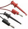
These checks are a lot easier and much safer if you have mini grabbers on your meter probes.

Minigrabbers.jpg

- Pete
 
Also be sure you are identifying the pins correctly on both boards. They may be a mirror image left and right.

- Pete
 
easy one to try .. play some music or a steady test signal if you can as easier to make comparisons .. plenty of apps for this if you have a pc or a phone ..1khz sine is standard ...
measure AC volts at both pin sevens .one for each channel .. remove speakers first as 1khz is annoying to the ears .
 
On the left channel I get basically 0 (.005 V) and the right (working) channel I get numbers that very as I turn the volume knob. The left channel never changes.
 
There is no easy way to know what's wrong with the board. The schematic in the service manual has voltage test points. Checking them will help narrow down the area of the fault.

- Pete
 
Since you have a good driver board for comparison, remove both boards and test resistor values board to board. Since they are in circuit, they won't necessarily match the schematic values but should be pretty close board to board. Do this before you try measuring voltages, it's a lot safer for you and the boards. If you find values that don't match bad to good, remove and check that resistor. If it checks good off the board, look at surrounding components.

- Pete
 
It only took me two months to pull the boards out and start checking resistance values:). I have found that R17 on the left board (not working) is open, while r17 on the right board is 10.91 k ohms in the circuit. Working on getting an iron at school to remove it and test outside of circuit. Would you recommend ordering a different size resistor or is that the correct size for the circuit?
 
R17 should measure 150 ohms . 1/2 watt .
what are the colour bands on it ?
if you identified it correctly they are both bad .
watch out for the idle bias after changing them ..use a DBT .
 
Those measurements are still in the circuit. You are correct it is a 150 ohm (Brown green brown) but I will take them out asap
 
might just be marginally working on the side that works .. resistor should measure lower in circuit if anything . never higher unless there is charge in the capacitors doing strange things .
 
R17 and R20 are fusible resistors and need to be replaced. They are 150Ω.

However, the amplifier will still run and pass audio when those resistors drift high, you just can't set the bias.

If the resistor os completely open, then it will not operate, no bias, no audio.

Replace with 150Ω 500mW (1/2watt) Metal film resistor. Do them all, on both channels, R17 and R20.
 
I removed R17 and same results as in circuit. Left channel is completely open and right channel is 11 k Ohms. The new resistors are on the way
 
did you go over every other resistor ?
Why? These are the only fusible resistors in these driver boards, there are no other culprits worth looking at right now.

We need to get R17 and R20 replaced on both boards and then see where we are at then, I work on these amps all the time, and these are the only resistors that cause problems, unless there has been a catastrophic failure.

One thing at a time!!
 
Back
Top Bottom