• The move to the new server is done. There are some software and database maintenance updates in process. This has us passing the hat around to help out. We appreciate any donations. Seriously, even a dollar helps. The payment page may be found here - https://www.audiokarma.org/support.html

Sansui multiplex problem

Carbsandcaps

Super Member
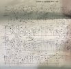
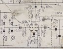
Working on a Sansui 1000 (not 1000a) tube receiver. When in multiplex mode one channel is muffled and slightly lower than the other. I’ve traced it to the 12au7 tube I’m assuming that splits the stereo signal. I swap the inputs to the grids and it does not swap channels. I swap the outputs at the plates and it follows the channel so it’s something at the tube itself. All the resistors test good. The input and output capacitors have been replaced. There’s 130v in the plates and 90v on the cathodes. There’s a potentiometer between the cathodes that I’m not sure what it does. It seems to be a balance but nothing is labeled. IMG_3393.jpegIMG_3394.jpeg
 
Register to hide this ad
That 12AU7 isn't doing the splitting. Just amplifying the signal and pushing thought the filters following. The demux action is happing the diode matrix before the the 12AU7.
 
I think that balance pot is the stereo width control? Possibly thats set wrong. But yeah other than the pot its basically just a dead common triode amplifier section. Output from one pair of diodes to one grid, output from the other pair to the second grid. If the pot is set too far wrong it will act funny, but the rest of it would just be either the tube itself, or off-value resistors or caps around it. If the caps have been changed and the resistors checked, there isn't all that much else it could be.


also don't forget those filter networks after the tube. If switching the connections at the plate changes it, you may have a problem between the plate and the L and R outputs. If those filters are packaged deals with just the legs available you can kinda check through it leg to leg for resistance and capacitence. Won't be entirely accurate but you should be able to compare results channel to channel easy enough.

a quick and dirty check, jumper pin 1 on each network together. If there is no change in the sound, its after that jumper. If it changes, its before the jumper.
 
wow, the 1000 SM schematic is different than what you have for that model. It labels that 12AU7 pot VR9, and step 5 of the MPX alignment has one use it to do the standard separation adjustment - play a tone on one channel, use the VR9 50k pot to minimize the other channel. I got my 1000 SM and schematic at hifiengine. They have the 1000A too
Step 5 calls it "VR", but it's the only pot available on the top deck in the MPX area, clearly labeled in the SM picture.

I would clean the tube pins, and swap in another tube at this point. It's very likely the pot is bad otherwise. It's 50k, so swapping in two equal value resistors close to 25k each would let you replace the pot for diagnostics. Or use a 50k pot laying around there.

Also note the SM1000 MPX has different 12AU7 resistor values from cathode to gnd - 15K versus 50K.
Was this a fix? With the same 20k plate resistors, changing It should bias the tube to idle with more current, but also likely gives the separation more adjustment range. Check the two 12au7 grid to gnd voltages. These DC values should change as you adjust the pot back and forth, going up one way, and down rotating the other way.
I would also replace those 10M resistors with low noise drift free units. They could be flaky, too no matter how they test. One could be drifting like crazy with elevated temps.

 

Attachments

  • 12AU7_MPX.PNG
    12AU7_MPX.PNG
    354.6 KB · Views: 3
separation, thats the word I was after, not width. Brain fart, but yeah it adjusts that. Too far one way and you get mono, too far the other way and you get this odd inverted phase thing, in the right position it gets max L-R and R-L separation. Sometimes those figures won't be identical and finding a happy spot where its equal going both ways can sound better overall.
 
Ok so this was really dumb on my part. I looked some more into it and found it was doing it with every input. Eventually after hours of switch thing left to right I found that it was in the loudness control. The volume pot has a tap (maybe 25-30% on the sweep) that comes off and goes to the loudness control. The wire for one of the channels came off the volume pit after I removed it for service.

However I am very th awful for the explanation of the balance pot. I was wondering about those 10m ohm they test good but seems like with such a large resistance they would be susceptible to almost anything.

I did end up turning the pot just to see what happens and it goes from ok to unlistenable. There paint on it so putting it back where it was is easy.

I thought the diodes were what separated the left and right signal. Radio still boggles my mind how so much info can be carried on a wave and then split up and sent where everything is supposed to go.
 
Multiplex is the confusing part to me. Up to the ratio detector im good, i even get the pilot tone and the 38kc oscillator locking to it but at that point its voodoo.
 
More than you ever wanted to know


Back
Top Bottom