• The move to the new server is done. There are some software and database maintenance updates in process. This has us passing the hat around to help out. We appreciate any donations. Seriously, even a dollar helps. The payment page may be found here - https://www.audiokarma.org/support.html

Sansui QRX-7001 F-2436 driver board: strange resistor values

metaphile

New Member
Update: I did not lift one leg of the resistors before measuring and therefore read the wrong values because the resistors were still in-circuit. Once I lifted one leg I read the right values. Measuring across the other resistors without lifting one leg gave me the right values so I incorrectly believed I could follow that methodology with all of them. Oops! :confused::oops:

TL;DR:
R-23, 24, 25, and 26 on both F-2436 driver boards in my Sansui QRX-7001 are reading around 83kΩ though their values should be 270kΩ (R-23, R-24) and 120kΩ (R-25, R-26). What gives? Should I swap them with the correct values?

Hey folks,

I've been working on restoring a Sansui QRX-7001. I'm currently using it as a 2-channel receiver and have re-capped all the boards in the power supply section and in the 2-channel audio path; I've also replaced all the 2SA726 and 2SC1313 transitors on the tone control board and the driver board w/ KSA992's and KSC1845FTA's, respectively, cleaned the switches and pots with deoxit, and a few other sundry things.

Bias and offset are near-perfect and stable -- the only issue I'm having is with a hiss from the (90dB sensitivity) speakers that is audible a few feet away and seems independent of the volume control. Seems to have gotten worse since I started working on it. I recently re-replaced the transitors on the tone control board to no avail and now am turning my attention back to the driver board.

I have left the rear driver board stock so I can have a control for experimenting with the front driver board that I have recapped.

The issue:

Anyhow, I checked all the resistor values on the F-2436 front driver board to ensure none had drifted. (I don't have any of the fusible resistors on the boards.) All were very close to the correct values (well within 5%) except for R-23, R-24, R-25, and R-26.

According to both the service manual & the markings on the transistors themselves, R-25 and R-26 should both be 120kΩ. According to the markings, R-23 and R-24 should be 270kΩ. Strangely, R-23 and R-24 are not listed in the version of the service manual that I have. I checked them and double-checked them on the first driver board, then checked and re-checked them on the second driver board - even used a second meter to ensure nothing was amiss. All 8 of these resistors on the 2 boards read somewhere in the 80-85kΩ range.

Additionally, the PDF copy of the service manual I am using was poorly scanned and so the resistor labels on the schematic diagram of the audio section are illegible. Thus, I'm uncertain of their role in the circuit. If anyone can share a better copy, or point me to a reliable place where I can buy or download one, I'd appreciate it.

So, some questions:

  • Does this make any sense? I have read that resistors either fail open or increase in their resistance. Why would these ostensibly 120kΩ and 270kΩ resistors ALL read around 80kΩ?
  • Can anyone tell me what role these resistors play in the circuit (or point me to a better copy of the schematic diagram of the audio section of the QRX-7001)?
  • Finally, any harm - or benefit - in replacing these with the marked values?
Thanks in advance for the help - it's been a huge pleasure lurking here and absorbing so much wisdom from everyone on this forum.
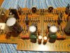
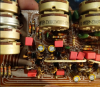
f2426_r23-26.jpg
f2426_r23-26a.jpg
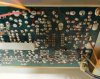
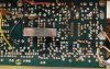
f2426_resistors.jpg
 
Last edited:
Register to hide this ad
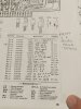
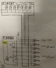
Welp, I found a legible schematic diagram of the F-2436 board from a Sansui 8080 service manual and highlighted the resistors below. The values listed here confirm that these should be 120kΩ and 270kΩ, respectively.

I'm still new to this hobby and haven't learned fully how to read these circuit diagrams - but given that R25/26 are tied to the base on differential pair TR04, it seems to have an - erm - rather important(?) role to play as far as the voltage being fed into that transistor. Seems like this value being off could throw off the balance between TR01 and TR03 / TR02 and TR04? R23/R24 I'm not sure about -- I'm going way out a limb here but is it part of the negative feedback loop?

f2436-schematic.JPG
 
Alright, I did a dumb thing but apparently since I'm not a moderator I can't delete this thread :oops:

I was measuring the resistors on the board across the two legs without lifting one to take it out of circuit. Once I did that, they read the correct values.

So, moderator - please feel free to delete. Or save this post for posterity so that others may learn from my mistake. :biggrin:
 
You are correct, the four marked resistors in your schematic post #2 are extremely important resistors. R25 & R23 and R26 & R24 are actually connected in parallel. A quick calculation of the product of a 120KΩ resistor in parallel with a 270KΩ resistor results in 83.076KΩ. ;)
 
Suggests oscillation, or leaky capacitors C15 & C16. ;)
I noticed R51 was OK in one photo, and burnt in the next. All of the electrolytic caps should be replaced. They have been already too so if that resistor burned after the caps were changed, there is definitely something awry.
 
Last edited:
Welp, I found a legible schematic diagram of the F-2436 board from a Sansui 8080 service manual and highlighted the resistors below. The values listed here confirm that these should be 120kΩ and 270kΩ, respectively.

I'm still new to this hobby and haven't learned fully how to read these circuit diagrams - but given that R25/26 are tied to the base on differential pair TR04, it seems to have an - erm - rather important(?) role to play as far as the voltage being fed into that transistor. Seems like this value being off could throw off the balance between TR01 and TR03 / TR02 and TR04? R23/R24 I'm not sure about -- I'm going way out a limb here but is it part of the negative feedback loop?

View attachment 1630882
Also note there are a few variations of this board, and undocumented changes since the schematic/SM was printed. Always go by what is on your particular board when replacing anything.
 
I noticed R51 was OK in one photo, and burnt in the next. All of the electrolytic caps should be replaced. They have been already too so if that resistor burned after the caps were changed, there is definitely something awry.

Wow, good eye -- I appreciate you catching the burnt resistors. I hadn't noticed! I'm still new to this hobby and have only blown a couple of resistors so far (on another project) and they - well - they exploded so there was no ambiguity there whatsoever. When I first inspected these boards I honestly I thought those were markings from a permanent marker. Upon closer inspection, they are indeed burnt. Good news is that this happened before I recapped the board.

Suggests oscillation, or leaky capacitors C15 & C16. ;)

I'll replace C15 and C16 as well when I replace those resistors. I don't have a capacitance/ESR meter to test with so may as well just be on the safe side. Unless anyone recommends otherwise, I will replace the caps with .1uF Wima MKS2 metal film. As far as your oscillation comment is concerned: I haven't bought a scope yet so I feel like I'm flying blind with some of my troubleshooting. But I think a scope purchase is on the horizon. My working space is limited so on the one hand a newer, smaller inexpensive digital scope seems prudent but on the other hand a used Tektronix 465 seems a good value.

While I'm at it: last night I think I may have made a mistake and hastily put the QS matrix and phase control boards in the receiver with one of the leads or solder joints on the backside of one of the boards making contact with the chassis (not sure that this is what happened but I'm speculating because that was the only thing I touched last night. I haven't recapped those boards yet but have the parts on order). While running the receiver I noticed the telltale smell of "magic smoke" and it seemed to be coming from the tone control board, which I have already re-capped and replaced transistors. Upon close inspection, I was unable to visually identify anything burnt. Smell seemed to be coming from the section of the board dedicated to the rear speakers, and I was only running one set of speakers at the time. Anyhow, I shut down the receiver very quickly and nothing popped or anything. Any tips for identifying which component may have let off the smell? Since none of the resistors are visually burnt and the new caps I installed all look fine, I was thinking maybe to just replace the transistors.

I carefully re-seated the QS boards and ran the receiver some more with the front speakers - no audible issues or smell. Audio still sounded fine. Pots worked. Haven't tried it with the rear speakers yet, partly because I haven't recapped the rear driver board nor set the bias and DC offset for the rear channels.

Smell seemed to be coming from here:

upload_2019-10-2_22-27-36.png

Thanks so much for the help! Will update the thread once I've replaced the parts.

P.S. I'm sure many of you can relate to this, but my shipping bills to Mouser alone are on the verge of adding up to the cost of an brand new budget receiver. :rflmao:
 
Last edited:
I noticed R51 was OK in one photo, and burnt in the next.

Just to clarify, those two photos were taken simultaneously of the two F-2436a boards in the amp. The front driver board has been recapped and the transistors replaced with KSA1845FTAs. The rear driver board is stock, parts are on order.
 
Any tips for identifying which component may have let off the smell? Since none of the resistors are visually burnt and the new caps I installed all look fine, I was thinking maybe to just replace the transistors.

Welp, I found the source of the smell.

Guess maybe I was wrong when I said I didn't have any fusible resistors on this board. This must be R-601, mounted to the underside of the F-2428 Filter & Power Supply board right underneath and in parallel with R06, the 180Ω 2W resistor. I happen to have a "before" photo which confirms that this indeed is (was) 8.2Ω which matches with what's in the schematic. The cool part? I already bought a replacement resistor back when I was re-capping F-2428 and so for once I'm not spending another $8 at Mouser for a teeny-tiny shipment.

There's what looks to be some charring under the Tuner board (I will reflow all the solder where it may have been damaged/cracked by heat) which was the clue that had me looking at F-2428.

I'll keep trucking along here (I'm learning a lot!) but if anyone has any advice about other specific components to check that may have been damaged due to this resistor burning out, I'd love to hear it.

I'm a bit confused by the schematic versus the actual board traces: looking on the traces, R-601 ends up in the path to traces that lead to the pins for the F-2086 CD-4 main circuit board and are linked via a yellow wire to the F-2423 filter & switch circuit board and a red wire to the CD-4 sub channel circuit board. Before this fusistor burned out I actually flipped the receiver into CD-4 mode and it resulted in a loud pop and the protection relay disengaging the speakers. So... I wasn't planning on doing that again until I had recapped those boards and investigated a bit. Seems there may be a correlation here.

Copious graphics:

The resistor "before" (when I was initially re-capping F-2428):
r-601_before.JPG
R-601 "after":
R-601_after.JPG

R-06, the big 2W resistor in parallel:

f-2428-2W_resistors.JPG

R-601 in the schematic (as far as I can tell):

R-601_schematic.JPG

Versus R-601 traces highlighted:

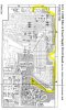
traces_highlighted.JPG

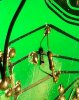
Lastly, charring under the tuner board:
bottom_side_tuner_board.JPG
bottom_side_tuner_board-1.JPG
 
Welp, I found the source of the smell.

Guess maybe I was wrong when I said I didn't have any fusible resistors on this board. This must be R-601, mounted to the underside of the F-2428 Filter & Power Supply board right underneath and in parallel with R06, the 180Ω 2W resistor. I happen to have a "before" photo which confirms that this indeed is (was) 8.2Ω which matches with what's in the schematic. The cool part? I already bought a replacement resistor back when I was re-capping F-2428 and so for once I'm not spending another $8 at Mouser for a teeny-tiny shipment.

There's what looks to be some charring under the Tuner board (I will reflow all the solder where it may have been damaged/cracked by heat) which was the clue that had me looking at F-2428.

I'll keep trucking along here (I'm learning a lot!) but if anyone has any advice about other specific components to check that may have been damaged due to this resistor burning out, I'd love to hear it.

I'm a bit confused by the schematic versus the actual board traces: looking on the traces, R-601 ends up in the path to traces that lead to the pins for the F-2086 CD-4 main circuit board and are linked via a yellow wire to the F-2423 filter & switch circuit board and a red wire to the CD-4 sub channel circuit board. Before this fusistor burned out I actually flipped the receiver into CD-4 mode and it resulted in a loud pop and the protection relay disengaging the speakers. So... I wasn't planning on doing that again until I had recapped those boards and investigated a bit. Seems there may be a correlation here.

Copious graphics:

The resistor "before" (when I was initially re-capping F-2428):
View attachment 1635158
R-601 "after":
View attachment 1635159

R-06, the big 2W resistor in parallel:

View attachment 1635169

R-601 in the schematic (as far as I can tell):

View attachment 1635162

Versus R-601 traces highlighted:

View attachment 1635163

Lastly, charring under the tuner board:
View attachment 1635164
View attachment 1635165
That resistor on the underside should be replaced with a 1/2w (non-Chinese) metal film. It obviously gets hot. The discoloring on the tuner board is from the carbon smoking.
 
Another question: there are many of these big white cement resistors on the amp. I've got two on each of my driver boards, two on the F-2428 power supply board, two on the tuner power supply board, and 8 on the F-2427 power board.

Would it be smart to proactively replace these, even if they read correct? (I should add that my DMM doesn't do so hot reading sub-1Ω resistors). If so, what type of resistor would be appropriate? Ceramic? Metal Oxide? Wirewound?
 
Another question: there are many of these big white cement resistors on the amp. I've got two on each of my driver boards, two on the F-2428 power supply board, two on the tuner power supply board, and 8 on the F-2427 power board.

Would it be smart to proactively replace these, even if they read correct? (I should add that my DMM doesn't do so hot reading sub-1Ω resistors). If so, what type of resistor would be appropriate? Ceramic? Metal Oxide? Wirewound?
They're needed for the wattage/heat they dissipate and are probably just fine. They are ceramic (or cement) wirewound and rarely go bad unless something else causes excessive current. Like a shorted transistor or something. Very few DMMs are accurate under 1 Ohm so as long as they read 1 or less, you'll be fine (if they are sub 1 Ohm). Both my 7001 (and a 6001) have all the original ceramic power resistors in them.
 
Oh, look at those ceramic resistors and check the lettering/numbers on them. If it looks like there is a faded spot, I would change it. That would be about the only indicator of one being too hot at some point.
 
Oh, look at those ceramic resistors and check the lettering/numbers on them. If it looks like there is a faded spot, I would change it. That would be about the only indicator of one being too hot at some point.

Great tip, thank you! So far they all look quite good by that standard. :)
 
Back
Top Bottom