mootej
Active Member
So I decided to do a recap for my Sansui SP-2000's. The story started here:
https://audiokarma.org/forums/index...2000-replacement-woofer.899787/#post-13427340
I also have access to an impedance-frequency analyzer of sorts so I thought I would do some measurements and post the results here. As an intro, the device will apply a voltage and measure the current required or apply a current and measure the voltage required at any frequency when I hook up the positive and negative test leads to a "device". With Ohm's Law (V=iR), if you apply one and measure the other, you can calculate the resistance at that frequency. Well, it's a little more complex (no pun intended) because technically, with an AC signal, you measure impedance, both the signal phase shift and the signal resistance known here as modulus. I usually set it up to measure 10 points per decade of frequency. 10 points between 10000 and 1000Hz, 10 points between 1000 and 100Hz, etc.
To start, the caps I need for the rebuild are 0.47, 2.2, 3.3, 8.2 and 22uF with at least the voltage required so the amp does not burn them out. In this case (approximately) the speakers are 8-ohms, the speakers handle up to 70W and ohms says P=V^2 / R so V= sqrt(70/8) = 2.95V.
Well, I end up getting a bunch of Solen film caps that are rated 250 or 630V. I read that it is good to bypass each of these caps with a 0.01uF capacitors (rated at 1000V!) in order to well, I don't know, I guess we'll see. I think it acts as a high pass across the cap to not lose the highs. I need to go back and read that post.
Anyway, I spent the night measuring the new caps. Here's what I get:
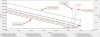
So this is a Bode plot, frequency along the bottom axis (1 Hz on the left, 1 MegaHz on the right). Up and down is the [modulus of...] impedance, 10 milli-ohms at the bottom and 100 Mega-ohms at the top. (both are log plots to fit everything in and yes, most audio works in logs because that's how your ears work). Wow, basic stellar capacitor performance, decreasing frequency, increasing impedance, just like a capacitor should work. Phase shift at -90 degrees just like a capacitor should work. No deviation below 50KHz, way above the audible. Some phase shift dropping off to zero at really high frequencies, way above the audible, inductive leakage! Low impedance at high frequency (generally under 1-ohm) and high impedance at low frequency.
Oh, by the way, two speakers, two sets of caps. Both sets tested exactly the same.
OK these are the new caps. Can't wait to compare new to old when I pull old beasties.
Back to the bypass caps, those little 0.01uF buggers that cost a bundle. I ran the little cap 0.47uF and big cap 22uF with the bypass caps in across them:
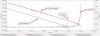
Well, at least in parallel with the other capacitor, they do not do much, maybe a little bit way above the audible frequencies for the large capacitor. Maybe they do more when they are in a tuned circuit with the inductors and resistors. I guess we'll see. Stay tuned...
Sorry, I'll try to get these plots a little more readable...
https://audiokarma.org/forums/index...2000-replacement-woofer.899787/#post-13427340
I also have access to an impedance-frequency analyzer of sorts so I thought I would do some measurements and post the results here. As an intro, the device will apply a voltage and measure the current required or apply a current and measure the voltage required at any frequency when I hook up the positive and negative test leads to a "device". With Ohm's Law (V=iR), if you apply one and measure the other, you can calculate the resistance at that frequency. Well, it's a little more complex (no pun intended) because technically, with an AC signal, you measure impedance, both the signal phase shift and the signal resistance known here as modulus. I usually set it up to measure 10 points per decade of frequency. 10 points between 10000 and 1000Hz, 10 points between 1000 and 100Hz, etc.
To start, the caps I need for the rebuild are 0.47, 2.2, 3.3, 8.2 and 22uF with at least the voltage required so the amp does not burn them out. In this case (approximately) the speakers are 8-ohms, the speakers handle up to 70W and ohms says P=V^2 / R so V= sqrt(70/8) = 2.95V.
Well, I end up getting a bunch of Solen film caps that are rated 250 or 630V. I read that it is good to bypass each of these caps with a 0.01uF capacitors (rated at 1000V!) in order to well, I don't know, I guess we'll see. I think it acts as a high pass across the cap to not lose the highs. I need to go back and read that post.
Anyway, I spent the night measuring the new caps. Here's what I get:
So this is a Bode plot, frequency along the bottom axis (1 Hz on the left, 1 MegaHz on the right). Up and down is the [modulus of...] impedance, 10 milli-ohms at the bottom and 100 Mega-ohms at the top. (both are log plots to fit everything in and yes, most audio works in logs because that's how your ears work). Wow, basic stellar capacitor performance, decreasing frequency, increasing impedance, just like a capacitor should work. Phase shift at -90 degrees just like a capacitor should work. No deviation below 50KHz, way above the audible. Some phase shift dropping off to zero at really high frequencies, way above the audible, inductive leakage! Low impedance at high frequency (generally under 1-ohm) and high impedance at low frequency.
Oh, by the way, two speakers, two sets of caps. Both sets tested exactly the same.
OK these are the new caps. Can't wait to compare new to old when I pull old beasties.
Back to the bypass caps, those little 0.01uF buggers that cost a bundle. I ran the little cap 0.47uF and big cap 22uF with the bypass caps in across them:
Well, at least in parallel with the other capacitor, they do not do much, maybe a little bit way above the audible frequencies for the large capacitor. Maybe they do more when they are in a tuned circuit with the inductors and resistors. I guess we'll see. Stay tuned...
Sorry, I'll try to get these plots a little more readable...