
• The move to the new server is done. There are some software and database maintenance updates in process. This has us passing the hat around to help out. We appreciate any donations. Seriously, even a dollar helps. The payment page may be found here - https://www.audiokarma.org/support.html

Sansui solid state 7000 repair, recap, and restore

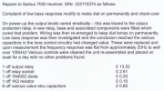
So I've taken my Sansui 7000 to a specialised technician with a reputation in the industry and he came back with the findings listed in the image below.

In the first sentence he states that "output levels varied erratically - this was traced to the output protection relay". I'm a bit confused as the 7000 is a capacitor coupled design. Any ideas what he's on about?!?
 

Attachments

  • Screenshot 2025-08-04 at 22.16.14.png
    Screenshot 2025-08-04 at 22.16.14.png
    620.9 KB · Views: 43
If it was never opened before, indeed very odd.

Many put in a timing relay just to get rid of turn-on and turn-off artifacts at cap coupled amps.
(Usually an elcheapo Chinese add-on little circuit card). So there is a possibility one was in if not knowing its history.
 
There's certainly no relay in a stock unit. The only protection is an SCR-type which many, myself included, disable. I would ask him to show you the old one & where it was located.
 
To my knowledge, the 7000 didn't have a relay. According to the serial number, your 7000 was built in November 1972 at the very end of the production run. That month Sansui started installing an updated tone board but the schematic still shows it as cap coupled with no relay.

- Pete
 
I've spoken to my man and he told me that someone who worked on the receiver before him had put a relay on the outputs.
He explained to me that of all things that are going to fail in units the mechanical things fail most often and relays are one of the things that can go wrong.
He also said that adding a relay on the output on cap coupled amplifier is not a thing he would do but people read things somewhere and think it's a good idea and do it. He has put the relay now in a socket so if it goes faulty again it can easily be replaced. If he would have told me when he found it I would have asked him to remove it but now I guess I'll let it be.
 
I've spoken to my man and he told me that someone who worked on the receiver before him had put a relay on the outputs.
He explained to me that of all things that are going to fail in units the mechanical things fail most often and relays are one of the things that can go wrong.
He also said that adding a relay on the output on cap coupled amplifier is not a thing he would do but people read things somewhere and think it's a good idea and do it. He has put the relay now in a socket so if it goes faulty again it can easily be replaced. If he would have told me when he found it I would have asked him to remove it but now I guess I'll let it be.
The nice thing with a relay, is if there is a time delay, you won't get any dreaded turn on thumps.
 
Thanks @dlucy for this thread. Was rereading it last night and post #41 was just what I needed! One of my incandescent dial lights was dim and have been meaning to change them out. I knew there had to be an easy way to get access to them, much appreciated!
 
Thanks @dlucy for this thread. Was rereading it last night and post #41 was just what I needed! One of my incandescent dial lights was dim and have been meaning to change them out. I knew there had to be an easy way to get access to them, much appreciated!
I have followed dlucy's excellent postings to restore my Sansui 7000. All caps on power, tone and amp boards have been replaced. All diodes on power board replaced. All Transistors on amp board replaced. Output transistors, voltage regulator and filter caps also replaced. It sounds good, but I am having trouble adjusting bias. I can only get it down to about 65 mA, by adjusting both VR802 and VR 801 full clockwise, spec says it should be between 27 - 33mA. I am checking mA at the fuse holders, with fuses out, volume all of the way down, on AUX, with no input signal, power limiter is ON. I have tried with speaker switch off and speakers connected, I get the same reading. Both channels behave the same way. I then tried installing a new trimmer at VR802 on one board, still can only get down to 65 mA. I checked the voltages on Amp Board that I can see in the schematic and they are all a little below spec, w/i 10 percent, except voltage coming off of the filter caps, a little high at 32v (spec is 30v, with power limiter on). Anyone with suggestions on what to check next?
 
if the new driver and output transistors VBE are the cause (many times new transistors have lower VBE than the old ones, you could try change R814 to .2.k and 815 to 2.7k, which puts the trimmer in another voltage region to regulate the VBE multiplier transistor..
 
Thanks for the advice! I put a 2K resistor at R814 and a 2.7k resistor at R815 and I was able to get the mA down to 59. I then switched the resistors, so the 2.7k resistor is at R814 and the 2K resistor is at R815, mA went down to 56 still a long way to go. Any suggestions about other resistor values to try? I do have a new 5K trimmer, could I put that in at VR802 (1K trimmer) to get more range for adjustment, without adverse affects?
 
You can try that, but my earlier recommendation should have been enough to get it down to even close to zero.
The VBE multiplier, having half of the resistance between collector and emitter at its base, should be able to reach something like 1.5 Volts which should be low enough to bring back bias to around zero, since there are three b to e junctions to overcome of two driver transistors and one output transistor.

So, apparently my recommendation was no good and did not work out.

Hopefully people more knowledgable also jump in because I am a bit in the dark.
 
I did try the 5k trimmer and it did not make any significant change. I will double check the other components I replaced on the amp boards. Thanks again for your reply.
 
I finally figured out my main problem, bad test meter. I should have started with the basics before assuming I had a major issue with the amp board. Anyway, my bias was actually too low, so I reduced R814 from 1.5k to 1.2k and was able to get the range to adjust bias between 27 -33 mA, per spec.
 
Back
Top Bottom