• The move to the new server is done. There are some software and database maintenance updates in process. This has us passing the hat around to help out. We appreciate any donations. Seriously, even a dollar helps. The payment page may be found here - https://www.audiokarma.org/support.html

Sansui SR 636 head shell connector pin pushed in?

oconnorweb

Active Member
Hey All -

I need some help.

I moved this from Turntable forum here to Sansui on the advice from another member.

I lost my right channel on a Sansui SR 636.

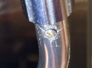
Looking at my head shell connector, it appears the right pin has been pushed into the arm tube. See photos. No idea how this happened. I do switch out head shells from time to time. Maybe that? Is this fixable?

Does anyone know if that pin which appears pushed in maybe can be pushed back into place from the other side and secured in some way? First I have to get to it.

How do I get the set screw loose holding the head shell connector? It is underneath the arm and I just can't get a screwdriver in a good spot to loosen it. Do I need to remove the tone arm to get the head shell connector removed so I can get a look at the pushed in pin from the other side?

I found this as a possible new connector:

https://www.ebay.com/itm/334026220978

How difficult is it to replace the tone arm wire? I have very average skills ;).

Thanks
 

Attachments

  • sansui 636.jpg
    sansui 636.jpg
    137.5 KB · Views: 9
  • sansui pin 2.jpg
    sansui pin 2.jpg
    77.1 KB · Views: 9
  • sansui pin 1.jpg
    sansui pin 1.jpg
    80.4 KB · Views: 9
Last edited:
Register to hide this ad
Just an idea, take a tooth pick and put a small dab (very small) of super glue on the end and insert carefully not touching anything else but the face of the button.
Hold it there for about 30 sec. and see if you can pull it back out. if it works you can take something sharp to clean the little spot of glue off it while holding it with tweezers and making sure you don't push any other one in. If it don't work your no deeper in trouble then you already are, sadly.
 
Thanks for the suggestion. I may resort to that but I’d like to pull off the connector/collar and see what it looks like on the other side. I expect the 4 wires attached to the pins. Maybe I can push the misbehaving pin back into place?

I guess now I’m looking for help on how to get that connector/collar off. That holding screw is stubborn and I do not want to strip it. Seems already compromised by maybe someone long ago messing with it.
 
Thanks for the suggestion. I may resort to that but I’d like to pull off the connector/collar and see what it looks like on the other side. I expect the 4 wires attached to the pins. Maybe I can push the misbehaving pin back into place?

I guess now I’m looking for help on how to get that connector/collar off. That holding screw is stubborn and I do not want to strip it. Seems already compromised by maybe someone long ago messing with it.
You need a proper JIS screwdriver (different than Philips screwdriver) to release the screw. I don't know how much extra wire is behind the socket to allow removing it, you might end up pulling other pins as well. I think 0.8mm standard solder fits into the pin hole, you can try cut it to missing length to make a contact and putting a small piece in the pushed in hole, carefully, not to push it more in, and get it working. If you never worked on tonearms, I don't recommend it to learn on this one.
 
Thanks CrSens. I ordered the solder. Comes tomorrow.

I assume you are suggesting to just place the cut piece of solder in the pin hole rather than heat up the solder and try and get it to adhere to the pushed in pin?

Lastly, if this doesn't work, I will take it to my tech. Should I order this for him to use or is it possible he can repair what I have? https://www.ebay.com/itm/334026220978

Thanks a lot for responding.
 
Thanks CrSens. I ordered the solder. Comes tomorrow.

I assume you are suggesting to just place the cut piece of solder in the pin hole rather than heat up the solder and try and get it to adhere to the pushed in pin?

Lastly, if this doesn't work, I will take it to my tech. Should I order this for him to use or is it possible he can repair what I have? https://www.ebay.com/itm/334026220978

Thanks a lot for responding.
Yes, just place a piece of solder to make contact, no actual soldering. Try to make as nice cut as possible.
Tech could probably repair it if he opens the bottom of the turntable and pushes in the existing wire through the tonearm post as he pulls out the connector to fix it. But I am not sure, maybe there is enough wire slack behind the connector already so it is not necessary, and maybe the wire is tight when it transitions from post to tonearm tube so it is not possible to move it here without removing the tube from the post.
The ebay connector might work, but installation might require tonearm disassembly also to pull the wire through.
 
You would think these contacts would be spring loaded but, I get the feeling their either not or the spring has maybe broken.
Either way putting anything in there to take up the space and make contact may end up pushing it back more, so be very careful.
 
I might as well try the solder recommendation. What do I have to lose. As it is now, I will need to remove the collar one way or another.

Thanks.
 
You need a proper JIS screwdriver (different than Philips screwdriver) to release the screw. I don't know how much extra wire is behind the socket to allow removing it, you might end up pulling other pins as well. I think 0.8mm standard solder fits into the pin hole, you can try cut it to missing length to make a contact and putting a small piece in the pushed in hole, carefully, not to push it more in, and get it working. If you never worked on tonearms, I don't recommend it to learn on this one.
CrSens -

Solder arrives today. If that does not work, I was looking at the head of the screw again. I am considering taking off the table bottom to see if I can push some excess wire into the tube so that if I am able to pull off the collar, then all the pin wire connections will stay intact. Then I will see if I can put that pin back in place. If not, I can buy a matching collar for this Sansui SR 636 table. Attach the 4 wires and put the collar back on. Sound feasible?

Here is a pick of the head of the set screw. Blurry, I know. But does it look like a JIS head to you? It still looks like a flat head to me.....For my plan to work, I have to remove that collar.

Thanks -
 

Attachments

  • collar screw.jpg
    collar screw.jpg
    71.6 KB · Views: 14
Last edited:
CrSens -

Solder arrives today. If that does not work, I was looking at the head of the screw again. I am considering taking off the table bottom to see if I can push some excess wire into the tube so that if I am able to pull off the collar, then all the pin wire connections will stay intact. Then I will see if I can put that pin back in place. If not, I can buy a matching collar for this Sansui SR 636 table. Attach the 4 wires and put the collar back on. Sound feasible?

Here is a pick of the head of the set screw. Blurry, I know. But does it look like a JIS head to you? It still looks like a flat head to me.....For my plan to work, I have to remove that collar.

Thanks -
It is a flat head screw, I was so sure it is JIS I did not even check.....
Your plan sounds good. You can try liquid wrench spray of freeze off or similar to loosen up the screw, just make sure it does not drip on the plinth special finish coat.
 
The .8 solder was too thin. My guess is that those pins are closer to 1.2 MM?

Anyway, I got the set screw removed with the some Blaster. Didn't even strip it. Took some time to get the socket connector pulled out. Of course all the wires remained in the tub. Looks like it will need a rewire job by my tech.

So I am looking at replacing that socket connector.
You would think these contacts would be spring loaded but, I get the feeling their either not or the spring has maybe broken.
Either way putting anything in there to take up the space and make contact may end up pushing it back more, so be very careful.
You were right. Spring loaded. Not sure what took me so long to push in the other pins with a paper clip. The bounced right back out. Except for the broken one. So is that common to have spring loaded pins? I am looking to replace the socket to give to my tech.

Thanks
 
The .8 solder was too thin. My guess is that those pins are closer to 1.2 MM?

Anyway, I got the set screw removed with the some Blaster. Didn't even strip it. Took some time to get the socket connector pulled out. Of course all the wires remained in the tub. Looks like it will need a rewire job by my tech.

So I am looking at replacing that socket connector.

You were right. Spring loaded. Not sure what took me so long to push in the other pins with a paper clip. The bounced right back out. Except for the broken one. So is that common to have spring loaded pins? I am looking to replace the socket to give to my tech.

Thanks
The solder fix was not supposed to be a tight fit, just to fit in the hole and make contact. If necessary adding a bit of blue tack on the side to secure it.
 
Back
Top Bottom