• The move to the new server is done. There are some software and database maintenance updates in process. This has us passing the hat around to help out. We appreciate any donations. Seriously, even a dollar helps. The payment page may be found here - https://www.audiokarma.org/support.html

Sansui TU-217 - solder/recap experts please help

jbay0310

New Member
Hello, I've been lurking quite a while and decided to tackle a recap of my TU-217 (that I just picked up) with help from the FM Tuner Info website and various threads here on AK. First of all, thanks to this community!

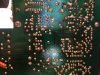
Normally I'd search the forum but this concern is specific to my board. I have attached several pictures for reference.

Here is my question:
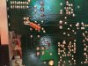
Did someone goober up the original solder flows on the back of this board? I can see what I believe are some repairs (you can see a few caps and resistors actually flowed to the back of the board rather than to the front...).

The tuner seems to be functional as-is but I wouldn't say it sounds "great," just okay. I'm new to this so there may not be any problems with this board at all. Just wanted to double check with some experts first.

ps - if I am using the wrong vocabulary to describe some of this stuff please correct me! Thanks.
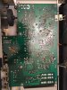
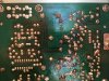
IMG_3247.JPG IMG_3248.JPG IMG_3249.JPG IMG_3250.JPG IMG_3251.JPG
 
Register to hide this ad
Looks exactly like mine did before a recap. Those tacked on parts aren't repairs, more so modifications that were made as production went along. This is something Sansui was known to do.
Great tuner for its cost, bummer the dial scale isn't illuminated.
 
The tuner seems to be functional as-is but I wouldn't say it sounds "great," just okay.
And thats about as good as they get, low end of the production range, and as far as that goes they are okay....
They are perfectly fine with a good strong signal, but selectivity and sensitivity is not great....
 
Call it a $50 lesson for my (pending) AU-717 recap! And hey, I'm already learning - ordered some replacement caps that were 100uf instead of 10uf by mistake. Duh.

If I get some nice "Sunday brunch" radio out of it I'll be more than pleased. :music:
 
Welp. I need some advice.

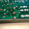
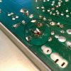
I tested the tuner for sound after the recap, and one channel of audio wasn't coming to my amp. I looked over my soldering again. I had cleaned the glue off C102 and C103... unbeknownst to me, in my effort to get the glued caps out, I must have lifted the trace from the back of the board. So when I soldered the replacement into C103 it came off the board. It still looks intact. Pics here:

IMG_E3255.JPG IMG_E3257.JPG

Two questions:
1. Could my problem of not having both channels of audio be related to this? I hope so. I attached a PDF of the board layout in case that helps.
2. Can I fix this? I was reading about an "epoxy" method for a lifted trace; is that the recommended solution?

I assume the best thing to do is remove that cap in C103, repair the trace, then remount the cap and try for sound again. Help would be appreciated.
 

Attachments

The missing channel is something else - that cap is a power supply filter and looks to be connected (albeit not well) anyhow...
 
Im not if you have rectified this but some areas to the top-right of your original pic 2 (in your first post) shows component leads that need to come thru the PCB to the solder-side more (based on the angle I am seeing that pic at, anyway) and they need to be reflowed. These are component legs not making proper contact with the tracks.

There are variosu ways to fix the problem that you have with your post 4 - yes its fixable but what I would do (from my own dodgy soldering experiences) is:

- Remove all the solder in that area & remove the component,

- Check carefully that the track still has its integrity and isnt cracked/broken,

- Cut off the area of lifted track,

- With a small sharp screwdriver, scrape off a few mm's of the green layer from the new end of your track - tin this area with solder,

- Solder in a new component and use a few mm's of the new component leg to connect to your newly-exposed area.

It works a treat if you do it right.
 
As long as you are in there, there a few transistors that are known to be noisy in the AM audio path. They cost pennies to replace.

TR 05, 09) 2SC1313(F,G) (F on PCB) new part ==>> KSC1845FTA
http://www.mouser.com/ProductDetail/Fairchild-Semiconductor/KSC1845FTA/?qs=UMEuL5FsraDCmxWozTypUA==

TR 06) 2SA726(F,G) (F on PCB) new part ==>> KSA992FTA
http://www.mouser.com/ProductDetail/Fairchild-Semiconductor/KSA992FTA/?qs=sGAEpiMZZMshyDBzk1/Wi8oN7VHZ91OkoO4jKvCu2tk=

TR 07, 08) 2SC945(P,Q) (P on PCB) new part ==>> KSC945CGTA
http://www.mouser.com/ProductDetail/Fairchild-Semiconductor/KSC945CGTA/?qs=sGAEpiMZZMshyDBzk1/Wi8oN7VHZ91OkACq8UyJR7ds=
 
Last edited:
your original pic 2 (in your first post) shows component leads that need to come thru the PCB to the solder-side more... and they need to be reflowed.

Thank you, I will find some YouTube tutorials and get to work.


- Remove all the solder in that area & remove the component...(etc.)

I have seen this method called for on some PCB repair tutorials. I will give this a shot, thanks for the reply.


As long as you are in there, there a few transistors that are known to be noisy in the AM audio path. They cost pennies to replace.

Great advice, thank you for the links as well. I am also planning to replace the resistors (R101, 102, 103, 104, 106) surrounding the power reserve caps (C102, 103) because of possible glue corrosion.


In terms of finding the fault in having only single channel audio, I'm double checking all my soldering and I'll figure out how to trace the problem backwards. It was putting out both channels before I recapped, so I'll take my lumps and troubleshoot. BTW this has been a great learning experience, thanks to y'all for helping me. I will update if/when I sort out these issues.
 
Last edited:
Back
Top Bottom