• Please note that Audiokarma will be offline briefly for updates early on Monday morning, September 28th.

Sansui TU-9900 power supply issue?

KeithD

AK Subscriber
Subscriber
My Sansui Tu-9900 has been working great since I got the lack of stereo fixed a while back.

One thing I've noticed, after being on for a few minutes, there'll be a "glitch" where the sound drops out. It's only about half a second. Signal strength meter drops, then sound and signal strength come back. Everything else is fine. When looking at the SM, I noticed TR04 is a 2SA726, which are known to be problematic. Not sure if the PS board is the source of the issue (maybe tuner board is momentarily loosing power) due to a bad transistor? I looked on the Tuner Information Center site for the recommended replacements for the PS board. They do not list TR04 as one that needs replacing, so not sure if that would really be the source. They do mention TR01 and 02. They do recommend replacing all of the e-caps, some with MUCH higher values. Is that really needed or wise? Any advice would be appreciated. Getting this issue solved is my next project!

Got the tuner matched with my AU-9900. Makes a great pair!
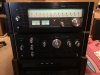
IMG_0908.JPG
 
Register to hide this ad
Monitor the power supply voltages at power up since that is when you say it happens. How you monitor depends on what test equipment you have and how long the glitch lasts. A scope is good to use as it can be triggered with a change in level. A DMM might be adequate depending on the glitch length. 2sa726 are reported by many as potential problems, so changing them would be a shot gun method. It might not solve the problem this is why monitoring where the fault lies and determine where to look, what are the possible components. If the PS is original it certainly would be a good idea to rebuild it considering its age.
 
Last edited:
Yes, I was thinking it would make sense to rebuild the PS anyway. The tuner is all original components. I was just thrown off by the cap recommendations on the TIC. I certainly can monitor voltages on the PS. Seems like the problem doesn't happen every time, and it's not at power up, but a few minutes after. Wonder if anyone has experienced the same issue on this tuner?
 
I'm pretty sure the mod, @Punker X, has extensive experience with this tuner. If he were to post his opinions, it might benefit others in the future.

In particular, I am interested in his (or other) opinions on the recap list on TIC, where all recommended replacement caps are much higher capacitance values than stock. I'd like opinions on that list before placing a Mouser order. I could also post a question in the Sansui forum, but thought I'd get more posts here.

Also, the general recommended replacement for 2SA726 is KSA992. Just want to make sure that his true in this PS application. I have a lot of KSA992FBU on hand.

Here's the PS recap list from the TIC (https://www.fmtunerinfo.com/DIY.html):


Panasonic FM series caps, KOA/Speer SP series Carbon Films or PRP Metal films. Whatever floats your boat. Yaego's are nice, too.

Power Supply: Spend some time here, it's worth it (Board #F2527):
D01/02 - Build two 2-diode bridge sections, Vishay IR Schottky - PN 11DQ10
D03/04 - Replace with Vishay IR Schottky - PN 11DQ10
C01 - .047 ceramic disk to .047/400 Polypropylene Panasonic ECQP-U
C06/07 - 470/35 to 1800/35 Panasonic FM
C08/09 - 220/25 to 680/25
C12 - 47/10 to 120/16
C13/14 - 10/16 to 47/25
C15 - 33/16 to 68/35
C16 - 220/16 to 470/25
ZD01 - 6.2V Zener to 1N823a (Temp Compensated) 6.2V
TR01/02 - regulators to OnSemi TIP41c
 
I go bigger on the caps then they suggest.. No problem with these suggestions. The sound dropping out could be PS or other things. Meter affected? Stereo lamp? Problems usually on the negative side.
 
I go bigger on the caps then they suggest.. No problem with these suggestions.

Great, thanks! I'm interested to learn why you increase the capacitance values, since in many applications the advice is to keep them the same?

Is it OK to replace TR06 2SA726 with KSA992FBU?

The suggestion is to replace several diodes as well, so I will need to put a Mouser order together for the caps, diodes, and replacements for TR01 and 02.
 
Last edited:
The sound dropping out could be PS or other things. Meter affected? Stereo lamp? Problems usually on the negative side.
The signal strength meter drops, sound cuts out. I had not noticed if the stereo lamp goes out or not. The dropout is only about half a second. Enough time for the signal meter to drop from 4 to about 1 before it moves back up/sound returns.
 
Also see TR05 is 2SC1312, which are also known to be problematic. Replacement KSC1845?
 
I was able to monitor the negative PS voltage (pin 8). Using the min/max feature on my Fluke DMM, I was able to record that when the "glitch" happens the voltage drops from -12 V to -6 V. Will monitor the positive side next time. The glitch happens within the first few minutes of power on (as components heat up?), so will need to wait before monitoring the positive supply.
 
Is it OK to replace TR06 2SA726 with KSA992FBU?

Yes

I'm interested to learn why you increase the capacitance values, since in many applications the advice is to keep them the same?

Really depends on where they are used. For main caps go and secondary I go big. Smaller one usually the same size. Coupling cap increase. Increase in size of the power supply gives you more reserve. Better bass, darker background. Increase in coupling cap size typically give better bass response. Bypassing with with a film caps helps the highs.
 
Thanks Mike. You are right about the negative side. Monitored the +13 V this morning from PS. When glitch occurred, the 13 V barely moved. Do you think this points to any particular component on the negative side? TR06? Would not be the first time I've had to replace a 2SA726 causing problems, though I've mostly seen these used in driver boards.
 
Update. Replaced TR06 (2SA726R) with KSA992FBU a few months ago, but it did not solve the power glitch issue. Just got around to replacing TR05 (2SC1312) with KSC1845FTA, and in the first test, the power glitch is gone. Legs on the 2SC1312 had oxidized to black. Hopefully, that solves the issue. Still plan to do a recap after I put in my next Mouser order.

Thanks for the help @Punker X !
 
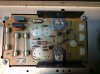
Yesterday I pulled the e-caps on the PS board. Then noticed D04 is missing (holes next to the Sanyo D314F transistor center top of picture). Should this be the case? Just wondering why that might not be there, and if I should put the replacement diode (SB1H100-E3/54) in?

IMG_2474.JPG
 
and if I should put the replacement diode (SB1H100-E3/54) in?
I wouldn't go putting in any 'missing' components until you know that it should be there. The tuner has been working fine? apart from the fault you have now fixed, don't proceed until you know for sure it should be there.

Update:
After a look at the schematic, it looks like that diode is pretty important, but I would still wait for some input by Mike (Punker X), or someone else 'in the know' before putting a replacement in.
 
Last edited:
I wouldn't go putting in any 'missing' components until you know that it should be there. The tuner has been working fine? apart from the fault you have now fixed, don't proceed until you know for sure it should be there.

Update:
After a look at the schematic, it looks like that diode is pretty important, but I would still wait for some input by Mike (Punker X), or someone else 'in the know' before putting a replacement in.
Agreed. C03 and C05 are also missing, but they are not on the schematic, so I don’t think they should be there, but I agree D04 is on the schematic and seems like it should be there. I also didn’t realize D01 and D02 are “double” diodes, so I did not order enough to replace those.
 
Don't currently have on here and honestly my memory is ****. I know I've taken pictures of the power supply before, but scrolling back through my photo's couldn't find one. It is on the scat and board diagram. I seem to recall it being there. Would put one in.
 
Don't currently have on here and honestly my memory is ****. I know I've taken pictures of the power supply before, but scrolling back through my photo's couldn't find one. It is on the scat and board diagram. I seem to recall it being there. Would put one in.

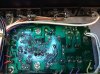
Thanks Mike. After reading your post, I thought I should look at the foil side of the PS board to see if there are any signs of a diode being in there. Here is what I found:

IMG_2476.jpg

Looks like D04 was put in place across R02 on the foil side. No sign of solder indicating there was anything in the D04 position. R02 and D04 are in parallel in the circuit, but not sure why they would have put that diode in like that?

Another question. The recommendation from fmtunerinfo for C008 and C009 is to move up from 220 µF to 680 µF. Somehow I mistakenly ordered 220 µF Panasonics (EEU-FM1E221BJ), and so do not have any 680 µF caps. The largest I have on hand are 470 µF (UPW1E471MPD6). Any suggestion on what I should do here? Options seem to be use the 220, put in the 470, or order the recommended 680?

Thanks!
 
Back
Top Bottom