• The move to the new server is done. There are some software and database maintenance updates in process. This has us passing the hat around to help out. We appreciate any donations. Seriously, even a dollar helps. The payment page may be found here - https://www.audiokarma.org/support.html

Sansui TU-999

KeithD

AK Subscriber
Subscriber
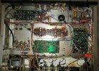
Picked up this tuner some months ago. It's working well, though I did have to replace the diode that regulates power for the stereo indicator. That repair made me think about a "recondition" for this tuner. I'm sure at least the power supply should be recapped; however, I can't find any threads on reconditioning one of these tuners. Also TIM does not have guidance on this particular Sansui tuner for how to recondition and/or improve it. Anyone done a re-cap on one of these and/or made some improvements/upgrades?
 
Register to hide this ad
Been trying to reply for a couple days. Looks like the server problems are now resolved.

Recommendations would be in order of impact.

1. Alignment
2. Recap the power supply. With good quality caps, Go head and increase the values here.
3, Improve audio coupling caps. Size can increase.
4. Recap the rest of the tuner. Keep values the same as the original.
 
Picked up this tuner some months ago. It's working well, though I did have to replace the diode that regulates power for the stereo indicator. That repair made me think about a "recondition" for this tuner. I'm sure at least the power supply should be recapped; however, I can't find any threads on reconditioning one of these tuners. Also TIM does not have guidance on this particular Sansui tuner for how to recondition and/or improve it. Anyone done a re-cap on one of these and/or made some improvements/upgrades?
Hi Keith, I did a lot of work to my TU999, when I have a bit of time I'll go back and see what I did.
I remember improving its frequency response in the final filtering stage. I got it sounding great.
But to do that you need a FFT spectrum analyser with transfer function.

Starting with the things Punker says is a great way to improve performance.
Be VERY careful with the slugs in those cans, especially in the MPX, they wont have been moved for a long time and this makes them very easy to crack.
I like working on and aligning discrete design tuners, very rewarding.

TU999 can be great, I regret selling mine!!
 
Thanks @Punker X and @kevzep , I did do an alignment when I first got the tuner. That went smoothly, and I was impressed with its ability to pull in stations after the alignment. SQ was good too. Will heed your words on the improvements. Will also replace D002 and 003 on the PS.

For the PS caps, how much larger would you go? Same question for coupling caps, and assume the small value e-caps should be replaced with films?

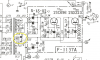
There is one large cap in the PS: C003 at 2200 µF/50V. Any recommendation for that position?

TU-999 PS.png
 
C003 looks to be chassis mounted. Can't remember what type. Would go as a high as 4700uf here or 3300 depending the type and what will fit with the space given. C016 just used for the stereo lamp and would keep the same value. C014 and 002 would take to 470uF.
 
C003 looks to be chassis mounted. Can't remember what type. Would go as a high as 4700uf here or 3300 depending the type and what will fit with the space given. C016 just used for the stereo lamp and would keep the same value. C014 and 002 would take to 470uF.
I have LKS1J472MESB 4700µF/63V on hand For C003. Assume you mean C015 and C015 to take to 470 µF. I have some UPW on hand with correct/higher voltages for those two.
 
I have LKS1J472MESB 4700µF/63V on hand For C003.
You'll find out fast enough if its okay, hoping the surge current is not too much to blow V10.
Temp replace V10 with a low resistive shunt and measure the initial turn on surge current with your DSO :)
UPW are fine too
 
You'll find out fast enough if its okay, hoping the surge current is not too much to blow V10.
Temp replace V10 with a low resistive shunt and measure the initial turn on surge current with your DSO :)
UPW are fine too
OK, well not going to put it in if it's not correct for the position. It's just what I have on hand.

Sorry for my ignorance, but I don't know what a low resistivity shunt is.
 
A shunt is a device usually having low resistance that is used as a means to measure voltage drop using I*R.
The resistance of the shunt depends on the current. You want as low as possible voltage drop but also within the measurement range and accuracy your meter measuring this voltage. For low current a 10 ohm can be used
 
HI Keith & team,
I just recapped my TU-999 and it sounds great. I will change the PS diodes as well. Picked it up a couple of weeks ago. Very nice tuner! Nice fat and rich sound to my ears. I did not recap the large 2200uF cap yet, but I think I'll leave the value, as is, and just increase the voltage with the new cap. So, where did you leave things Keith with your TU-999? If you recall, we chatted a bit about our Sansui Eights a while back. Also, as is probably the case with your TU-999, those transistors (2SC458, 2SC871, 2SC632) have an awful lot of semiconductor material leaking down the legs, and are also listed in the top 10 trouble transistor list. The TU-999 is chaulk full of those 3 transistors. Have you thought about changing those? I think the replacement is the KSC1845FTA's for all 3, but I think the Hfe gain is a bit lower than the originals. Also, I don't have the ability to do a full alignment, only a poor man's alignment (TC's, L's, OSC coils, meter centering, etc...) using the signal meter peaks. In other words, enough to get myself in a world of hurt if I'm not carefull. So, I dare not replace the transistors if it would throw off the alignment so much that I can't tweak it back without the proper equipment and knowledge. My unit sounds great the way it is, but......"fill in OCD reason here"...lol. Your thoughts, comments? Anyone welcome to comment as well. Thanks.
Tony

 
HI Keith & team,
I just recapped my TU-999 and it sounds great. I will change the PS diodes as well. Picked it up a couple of weeks ago. Very nice tuner! Nice fat and rich sound to my ears. I did not recap the large 2200uF cap yet, but I think I'll leave the value, as is, and just increase the voltage with the new cap. So, where did you leave things Keith with your TU-999? If you recall, we chatted a bit about our Sansui Eights a while back. Also, as is probably the case with your TU-999, those transistors (2SC458, 2SC871, 2SC632) have an awful lot of semiconductor material leaking down the legs, and are also listed in the top 10 trouble transistor list. The TU-999 is chaulk full of those 3 transistors. Have you thought about changing those? I think the replacement is the KSC1845FTA's for all 3, but I think the Hfe gain is a bit lower than the originals. Also, I don't have the ability to do a full alignment, only a poor man's alignment (TC's, L's, OSC coils, meter centering, etc...) using the signal meter peaks. In other words, enough to get myself in a world of hurt if I'm not carefull. So, I dare not replace the transistors if it would throw off the alignment so much that I can't tweak it back without the proper equipment and knowledge. My unit sounds great the way it is, but......"fill in OCD reason here"...lol. Your thoughts, comments? Anyone welcome to comment as well. Thanks.
Tony

I only recapped and replaced diodes on the PS (F-1137A) of my TU-999. At some point I will do some of the other boards (F-1236 audio amp board), filter cap, and other caps not on boards. Will look at transistors and replace the problematic ones. However, since all is playing well, this one is on a lower priority than some other units for service.

Agree this tuner sounds good and pulls in stations quite well, even without rehabbing the boards. Mine only needed the slightest adjustment on the alignment.

Glad yours is working well and the rehab is moving along. :thumbsup:
 
Thanks Keith,

I'll let you know of any further revelations I find if I decide to change some of the designated noisy transistors. For now I'm going to fight the urge, as it all sounds good as is. Once I get the new power supply caps in, I'll be done. Good luck to you as well.

Cheers

Tony
 
Hey guys, I'm working on a TU-999 for which I think the F-1137A has been tampered with. Would you by any chance have taken a pic of the wiring to your PS board that you can post?

And did you use 1N4004's as replacement diodes on that board?

Cheers
 
I did not take any pictures of the PS board, or if I did, I didn't save them. Here are the parts I replaced and what I replaced them with.

Screen Shot 2023-07-21 at 6.17.25 PM.png

Hope that helps.
 
Let me take a look and I'll see if I can take some pics for you. It may take a couple of days before I will have time.
 
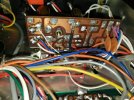
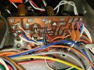
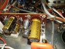
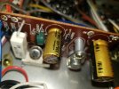
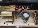
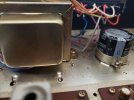
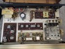
Here are some pics of the PS board and others. Hopefully, they will be of help to you in conjunction with the Schematic Keith provided.
 

Attachments

  • 20230725_130726_resized.jpg
    20230725_130726_resized.jpg
    137.5 KB · Views: 22
  • 20230725_130822_resized.jpg
    20230725_130822_resized.jpg
    138.2 KB · Views: 20
  • 20230725_130830_resized.jpg
    20230725_130830_resized.jpg
    99.7 KB · Views: 20
  • 20230725_130841_resized.jpg
    20230725_130841_resized.jpg
    91.9 KB · Views: 21
  • 20230725_131044_resized.jpg
    20230725_131044_resized.jpg
    128.9 KB · Views: 21
  • 20230725_130226_resized.jpg
    20230725_130226_resized.jpg
    97.5 KB · Views: 21
  • 20230725_130240_resized.jpg
    20230725_130240_resized.jpg
    82.9 KB · Views: 22
  • 20230725_130301_resized.jpg
    20230725_130301_resized.jpg
    156.1 KB · Views: 21
  • 20230725_131028_resized.jpg
    20230725_131028_resized.jpg
    183.6 KB · Views: 25
Back
Top Bottom