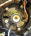
• The move to the new server is done. There are some software and database maintenance updates in process. This has us passing the hat around to help out. We appreciate any donations. Seriously, even a dollar helps. The payment page may be found here - https://www.audiokarma.org/support.html

Sansui XR-Q9 Turntable Restoration

Watthour

Electron Rancher - JS3600
Subscriber
I have a sample of the XR-Q9 turntable on the bench. The complaint was that the table would not drive, there was no automatic action, and the "computer" LED would simply flash until its timeout, then turn off. With the information which is available from several internet sources, I have been able to piece together the operation of the unit.

Various message boards, including AK , have threads regarding this unit and similar Sansui tables. Although there seems to be some contradictory information, it appears that the XR-Q9 tone arm mechanism is unique to the model. The XR-Q11 shares some of the design, but is a different mechanism, probably due to its track-memory functions. Other models are similar, like the XR-Q5/7 and FR-D4, but are not the same.

XR-Q9 Mechanism
www.wwdsltd.com/files/Q9-ToneArmDriveInstalled.jpg
Q9-ToneArmDriveInstalled.jpg

XR-Q11 Mechanism
www.wwdsltd.com/files/Q11-ToneArmDrive.jpg
Q11-ToneArmDrive.jpg

The summary finding is that many of the units reported as inoperative due to "failed computer" are most likely due to the failure of this mechanism and the logic not receiving the expected inputs within its time limits. A couple of the previous threads are very close to explaining the problems:

https://audiokarma.org/forums/index.php?threads/sansui-xr-q11-turntable.697486/

https://www.audiokarma.org/forums/index.php?threads/sansui-xr-q9-t-t-kind-of-long.10290/

https://www.audiokarma.org/forums/index.php?threads/repair-of-sansui-xr-q11-cueing-mechanism.246920/

https://www.audiokarma.org/forums/i...-turntable-speed-problem.362903/#post-4610323

More to come.

Links updated.
 
Last edited:
Register to hide this ad
Last edited:
The complete clutch and damper stack was disassembled and cleaned, then re-lubricated using the factory diagram where it indicated lubrication.

www.wwdsltd.com/files/Q9-CenterClutchAssembly.jpg
Q9-CenterClutchAssembly.jpg

The parts included several rubber "tires" used in the friction and damping arrangement, and those parts were treated with a rubber rejuvenator (Fedron) and re-treated after several hours. A second clutch "tire" is attached to the tone arm spindle, and is driven to position the tone arm onto the platen or back to the rest position.

www.wwdsltd.com/files/Q9-36_ToneArmClutchDrum.jpg
Q9-36_ToneArmClutchDrum.jpg

Another rubber "damper" is placed beneath the clutch driven gear and was also cleaned and treated.

Also visible in the picture is the photo-transistor/diode array and sector plate with its punched slots to create the position references for the "computer" logic controls. The factory manual is clear on how to test and adjust the 2.2V P-P waveform generated by this array so that the P-P voltage is correct and the offset is adjusted so that waveform clipping is symmetrical on both peaks. This is critical to the logic being able to detect and count the pulses near the end of the recording, and cycle the mechanism properly.

Once those signals were correctly set, the logic side of the unit functioned properly, and attempted to sequentially operate the tone arm motor, motor direction, solenoid clutch, and monitor the two microswitches to cycle and stop the mechanism appropriately. The still obvious problem was that the clutch stack was lacking sufficient torque capability to drive the cueing and arm position reliably. If the mechanism was manually helped along to overcome slipping, everything worked as designed.

Links updated.
 
Last edited:
The mechanism employs a solenoid-operated clutch to drive the tone arm position while simultaneously disengaging the center clutch mechanism so that the cueing is not operated while the tone arm is being positioned across the platen.

Item 16
Q9-16ClutchSolenoidAssembly.jpg


Q9-16ClutchSolenoidFrictionDisc.jpg


The parts of the center clutch assembly (above the solenoid clutch) are stacked up as follows:

Item 20
www.wwdsltd.com/files/Q9-20ClutchDamper.jpg
Q9-20ClutchDamper.jpg

Item 19
www.wwdsltd.com/files/Q9-19ThrustWasher.jpg
Q9-19ThrustWasher.jpg

Item 18
www.wwdsltd.com/files/Q9-18ClutchGear.jpg
Q9-18ClutchGear.jpg

Item 17
www.wwdsltd.com/files/Q9-17ClutchGearClip.jpg
Q9-17ClutchGearClip.jpg

Item 14
www.wwdsltd.com/files/Q9-14ClutchDrivenPlate.jpg
Q9-14ClutchDrivePlate.jpg

Item 13
www.wwdsltd.com/files/Q9-13ClutchDriverPlate.jpg
Q9-13ClutchDriverPlate.jpg

Item 12
www.wwdsltd.com/files/Q9-12ClutchDampingWasherReplacement.jpg
Q9-12ClutchDampingWasherReplacement.jpg

Item 11
www.wwdsltd.com/files/Q9-ToneArmDriveTopView.jpg
Q9-ToneArmDriveTopView.jpg

Links updated.
 
Last edited:
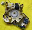
After cleaning, lubrication, assembly, and installation, the unit ran about half a dozen cycles in rapid succession in a completely normal manner. After that, the cueing would hesitate, and needed to be assisted in order for the clutch to transmit enough torque to perform its functions. It is apparent that the cueing mechanism created the greatest load on the mechanism, and that the assembly required more diagnosis and adjustment to function consistently. A spacer was fashioned to create additional pressure on the center clutch assembly when the tone arm drive clutch solenoid is not engaged. The presumption is that some wear in the friction discs has reduced the torque capacity of the clutch assembly.

www.wwdsltd.com/files/Q9-14AClutchShim.jpg
Q9-14AClutchShim.jpg

Once this is fitted into position I can report the results.

Links updated.
 
Last edited:
If you can get this working, you'll be the man of the hour so far as I'm concerned. I own several XR-Q9 and 11 T/T's and have been frustrated in trying to get them to work for 15 plus years. They were set aside a few years ago now as I haven't had time or the inclination to tinker with them any further.

FWIW, I've been convinced for a long time that this was mostly a mechanical issue, and had little reason to expect a logic failure. Also, the Q9 and Q11 use the same basic tonearm and control mechanism, though the X11 adds an infrared sensor to the end of the head shell to read the space between tracks on a record, and of course adds control logic to govern operation of that feature. Otherwise the Q11 Is nearly identical to the Q9.

I'll look forward to your updating this thread, as I'd love to get mine back in service and probably sell a few extra as I don't need 8 turntables. Most of the extra units were picked up hoping I'd find one that actually worked.
 
I remember some techs in the past having experience with this tonearm dilemma. This is a huge breakthrough for many of us with XR-Q9's and 11's. Possibly owners of similar models could also benefit from this information. Thanks for your perseverance and detailed pictures. Fever
 
XR-Q5 and 7 are similar but not identical in both the mechanism and the logic versus the 9 and 11.

This thread may finally be the solution we've been looking for. Really, the information presented so far is what I had always suspected. I've just never had the time and motivation to spend on the trial and error to get it working. Always some other higher priority that got in the way of tackling it, so it's nice that someone with the known-how is finally putting in leg work that I never could get around to, much to my own shame.

Watthour, if there is any way I can be of assistance, feel free to PM. For that matter, if an actual solution comes from this, I'd be happy to make a contribution to the cause for your efforts. After all, this has been a problem that has taunted me for 15 years. There would be some real satisfaction in finally getting these back into service.
 
Last edited:
Your contribution would be to continue sharing your experience and advice with the rest of the AK membership when needed, including me. You've obviously been up and down the street a time or two.
 
I've spent a bit more time on it today, experimenting with shims, spacers, varied lubricants, assist springs, no lubricant, and adjusting the solenoid clutch stroke. It will operate several cycles normally, then begin slipping again while attempting to move the cueing mechanism. It's closer than before, but not yet consistent enough to deem reliable. More experimentation and trial will be performed to attempt to achieve a permanent and reliable solution.
 
The most significant problem with the mechanism is the cueing system. The root of the problem is translation, and I've encountered this over the past several decades with a lot of eastern equipment, from Tanisaka, Mitsubishi, Mazak, Okuma, Mori-Seiki, and numerous other Japanese manufacturers. The factory instructions and exploded parts diagram indicates locations where lubricants should be applied, and there are errors and omissions.

Several lubricants were tried in this repair effort. White lithium grease, silicone grease, silicon (transformer) oil, mineral oil, graphite, molybdenum grease, white graphite, and no lubricant whatsoever. Shims and spacers were experimentally installed in various locations in an attempt to provide additional force to the clutches.

My best advice for repairing the mechanism is as follows (use the factory diagram as reference):

  1. Carefully remove the E-clips (11, 29, 17) holding the cueing cam follower (30), the center clutch upper disc (13), and center clutch lower drive gear/disc;
  2. Remove the associated parts and spacers (13, 14, 18, 19, 20);
  3. Clean everything with plastic-safe solvent (like isopropyl alcohol), wash with hot, soapy water, and allow to dry;
  4. Install the lower rubber "damping washer" (20) and apply a layer of dry graphite lubricant to its exposed surface. The factory instructions and diagram do not seem to indicate any lubrication for this section, but it is essential. Install thrust washer (19) and apply a layer of dry graphite to its top surface. Brush a light layer of dry graphite to the lower recess in the clutch lower drive gear ((18) and stack it in place;
  5. Install the E-clip (17) and clean the interior recess of the top side of the gear (18) and the rubber tire with alcohol. Allow the alcohol to dry and treat the rubber with rejuvenator (at least once) to help keep it pliable;
  6. Install the center clutch plate (14) to engage the flats on the drive shaft below. Be sure to install the disc with the serrated face against the rubber tire (down);
  7. Install the center clutch upper plate (13), its "damping washer" (12) and retaining E-clip (11). The "damping washer" had disintegrated in the unit I worked on, and it was replaced with a fiber washer, a metal washer, a paper shim, an o-ring, and finally a different fiber washer to perform correctly. This spacer should be 1mm thick, ±0.10;
  8. Lubricate the stem on the lower steel plate with a light coating of white lithium grease, then Install the driven cueing gear (32) and its retaining E-clip (31).

This is where things got more interesting. What I finally determined is that the cueing plunger (52) attached to the tone arm base does not contact the cueing cam follower (30) on its centerline, nor directly over the contact point of the follower to the cam. The years of use and wear allowed the upper cueing plunger to impart angular thrust to the cam follower, causing it to bind on the shaft which guides it. My solution was to install a compression spring over the boss on the lower steel plate to assist the cam follower upward at its outer end, thereby alleviating this binding. Several springs were fit in an attempt to determine a proper application. The result was a spring with 0.360" I.D., 0.020" wire, with a free length of 0.800" with a spring rate in fractions of ounces/inch. All this spring needs to accomplish is to lift the outboard (forked) end of the follower to prevent binding.

www.wwdsltd.com/files/XR-Q9-30ASpring.jpg
XR-Q9-30ASpring.jpg

Links updated.
 
Last edited:
Part II

It is highly adviseable to clean the gears (18, 21, 32), worm gear (6), and drive belt (4). Apply a light layer of white lithium grease to the gear teeth, the cam (32) and follower (30). It would also be prudent to apply rubber rejuvenator to the drive belt (4) and the tone arm upper drive clutch rubber tire (36).

CRITICAL! DO NOT follow the factory diagram where it indicates applying silicone grease to the tone are friction drive clutch and disc (10, 25). Clean these parts with alcohol to remove any trace of contamination, allow to dry, and apply rubber rejuvenator to the friction drive (25).

Multiple applications of rubber rejuvenator for all of these 40 year old parts may be necessary.

Lightly lubricate the cueing plunger assembly (52). While the drive mechanism was out, the lower ball bearing of the tone arm pivot is accessible, and a drop or two of light machine oil via a syringe is prudent.

Install the mechanism, plug in the 5-wire connector, and connect the grounding wire (if it was removed).
 
My assessment of this overall design is that almost all of the weaknesses, if not all of them, could have been overcome if the designers had selected a different gear ratio for the cueing drive mechanism. Instead of a large diameter gear over-driving the smaller diameter cueing cam/gear, those could have been reversed. This would have drastically reduced the torque transmission of the clutch array, and all the slippage would likely never have occurred. Sadly, it would have been SO easy to design this properly that it's a real shame that someone didn't think about it for just a few minutes more. I find this pretty typical of this vintage equipment, since by the 1980s when MBAs operated companies instead of engineers, the shift in mentality resulted in just this kind of end product.

EDIT: A really ambitious type with a 3D printer and time on their hands could probably resolve this by generating new parts. If I had a "spare" mechanism from one of these tables, the gear arrangement could probably be worked out and upgraded without too much difficulty.
 
Last edited:
Watthour, you have my thanks and respect for working this through. It's very unlikely I'd have hit on the exact combination of items that needed attention you did, especially the particulars of the lubrication and adding the spring. I'm pretty sharp, but the fix you engineered for this is beyond the limits of my knowledge to have developed myself, in all likelihood. And I say that as one who considers himself a pretty solid troubleshooter.

It may be a bit before I have time to attempt this myself, but will be saving this thread locally so I can reference it when I'm ready to start tearing into these.

Well done.
 
Hopefully you'll be able to resurrect a few of those tables in your stables. Send a message if you get into it and need more detail.

FWIW, I believe the spring I used from my assortment was either from a carburetor power valve or auto trans valve body - I don't recall, but the dimensions are provided above.

Also, it wasn't mentioned above, but I had the mechanism in and out of the table so many times that it was finally easier to add another ground wire from the chassis to one of the mounting screws. The original ground path was an array of wires soldered to a ground tab, preventing removal of the mechanism completely so that it could be set on the bench for serious work.
 
Last edited:
Back
Top Bottom