• The move to the new server is done. There are some software and database maintenance updates in process. This has us passing the hat around to help out. We appreciate any donations. Seriously, even a dollar helps. The payment page may be found here - https://www.audiokarma.org/support.html

Sanyo jcx 2900k bias / dc off-set.

anderslober

Yikes...not again!
Hello forum.............I have been playing around with the jcx2900k( a bit of 'plunder' from the US of A) a little bit. The unit is in very good condition and works....I
would like to set the bias and dc-offset to factory spec, but the SM has no mention of either. I have checked to see if I have all the pages....and yes....all the pages are there. There is 2 pages about tuner alignment, but nothing for the amplifiers.

Is there anybody out there with a jcx2900k that has done this?

On each of the driver boards, there are 2 pots, one labelled 'bias' the other labelled 'cent'. Just no mention in the manual about how to set it..........I have also searched the forums extensively, but there is very little info on the jcx2900k.

Otherwise, the unit is gorgeous! Thanks..................
 
Register to hide this ad
Hi--
I checked my copy of the SM and came to the same conclusion-- the SM doesn't include a section for the DC offset and bias adjustments. Sorry I can't help ya'. Maybe another AK'er can give guidance for these adjustments. Just a guess the Cent(er) is the DC offset. It is a nicely built receiver and deserves to be aligned. Enjoy. :thmbsp:
 
Do they show voltages in the schematic? You might be able to deduce the current if they showed voltages on the emitter resistors. Also, you probably would be okay if you stick to around 30 mA as this is pretty normal for solid state amps. If it were anything unusual, there would probably be information aabout it (I would hope).
 
ok.....thanks.....on the schematic there isn't much info either. I could probably set the dc offset to 0v by measuring on the speaker outputs.............but, how would I measure the bias?

It could be extremely helpful if another 2900k owner would measure his numbers and post them..................with pictures of the pots positions too......OR, is there an 'old' Sanyo tech out there who would know this?

thanks.......
 
hello again forum.......I have checked the 2600k manual too....no mention of bias or dc offset.

Please....is there anybody out there willing to pop the hood on their 2900k and take pic's of the pots? It would be a great help for a starting point for adjustment......thanks.

Much appreciated.......................are thier any tech's out there with good advice?

(the desperate)
 
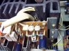
I attached a couple pictures of the driver boards and also checked the voltage across the emitter resistors. I don't have a manual so I don't know the correct values. Mine checked around 1-2 millivolts across either set of emitter resistors. It sounds great and runs cool so I am guessing it is close to being correct.
 

Attachments

  • 2900-l.jpg
    2900-l.jpg
    79.8 KB · Views: 149
  • 2900-r.jpg
    2900-r.jpg
    87.8 KB · Views: 135
FYI the centering pot adjusts the dc offset (adjust for as close to 0 voltage as you can) and the bias pot for idle current.
 
Hey Bill......my gosh.....thanks for your amazing help. EXACTLY what I needed.

I will fine 'tune' and report back........................................

Excellent........I owe you a beer or something!
 
Bill....regarding your first photo where your dmm probes are hooked up........are they hooked up correctly? Shouldn't the probes just be hooked up across one resistor....ie, both probes on one resistor?

Your probes are hooked to both resistors....one probe for each resistor.......are you then measuring across the emitter resistor? I hope you understand........just to confirm.

My pots are almost in the exact same position as yours.........I will hook up my probes on the speaker terminals for dc offset and on the resistors for bias........and report back......thanks again.
 
The emitter resistors are connected in series with one end connected to one of the P type output transistors emitter, and the other end of the other resistor to the N type output transistor emitter. You measure the voltage drop across the two resistors. Since this circuit has two output pairs you will have to measure the voltage voltage drop across the other two emitter resistors. If you want to know the collector current you can use the ohms law formula I=E/R where I=current in amps, E=voltage drop across the emitter resistor pair and R=resistance of the series connected emitter resistors.

If this sounds to complicated I would recommend that you just measure the voltage across the emitter resistors with a voltmeter connected as pictured, if it measures around 1-2 millivolts and the receiver sounds good and runs cool. I would leave it alone and don't worry about it.
 
In my spirit, there is no doubt that the "cent" adjust is for the offset. Adust with the negative voltmeter probe on the chassis, and the positive voltmeter probe on the output for each channel.

For the bias, I would advise to measure the voltage across each emiter resistor and not across a pair of emitter resistors. The reason is that there is a possibility that your probes might be on the emitters of the two NPNs and you may think that they are on the emitters of one NPN and one PNP. I would adjust the bias to ~25mV across each emitter resistor. The heat sink is efficient enough to prevent overheating of the amp with this bias current (50mA in each power transistor).
 
Bill/ecluser......thanks for the great info.........I will work on it a bit.........I will do both methods(across 1 resistor/across a pair of resistors) for measuring bias. The dc offset is easy enough..........just don't want to mess things up with bias..(and maybe fry something!)...........I will report back...........


I will also write all this good info into my 2900k service manual.
 
Last edited:
I powered ON and adjusted everything. Everything clicked as it should.

A few of the lamps are out.....

Speaker A lamp.
Speaker B lamp.

3 dial lamps.

FM lamp.

I think the speaker lamps and the FM lamp are the same (6.3v/65mA)....please confirm........thanks,

The dial lamps are 6v......I dont know the mA's.......can someone confirm....thanks.

In the photo.....the 3 lamps to the left are the dial lamps, the 2 in the middle are speaker lamps and the 1 on the right is the FM lamp.
 
Last edited:
Reviving an old thread. Just came across one of these fine receivers.Bias seems fine (stable 5 mv. on both channels) DC offset zeros out on the left,but on the right it adjusts to about 24 mv. and then stops! Is it safe to continue to use as is or should i dig deeper for the problem? Runs and sounds excellent,but there is a very small "thump" on turnoff. Any help would be appreciated.
 
Back
Top Bottom