• The move to the new server is done. There are some software and database maintenance updates in process. This has us passing the hat around to help out. We appreciate any donations. Seriously, even a dollar helps. The payment page may be found here - https://www.audiokarma.org/support.html

Scanned Service Manual for Marantz 2245

Paul Malloy

Active Member
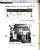
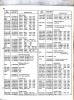
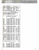
I purchased an original service manual for the Marantz 2245 and scanned it as a pdf. It appears to be searchable.

I would like to make it available to everyone, can somebody tell me how to upload it to the server? Original is about 18mb,and reduced is about 9mb.

If somebody would like to check it out to make sure it looks ok, let me know. I can redo the scans if needed. Add text too.

Paul


Pages from marantz 2245.jpg
Pages from marantz 2245_Page_1.jpg
Pages from marantz 2245_Page_2.jpg
 
Last edited:
Register to hide this ad
One way of doing it is the way I did my Marantz Transistor and Diode substitution guide near the top of the sticky section. I uploaded the file to my Google Drive, made it shareable, copied the link, and posted it in my thread. That way, someone can click on your link and download that file, no matter how large. There may be a way to get it into the akdatabase, but I'm not sure if it will take a file that big. Maybe browse around akdatabase.com and look for upload information.
 
Just printed it out and bound it. I printed out the three high resolution schematics as 11X17" and inserted the one for 1001-3300 for Page 20 on the full manual and the two higher serial number schematics for Page 3 & 4 on the smaller addendum. Also printed out a 18X24" schematic (found here in the library) for the above 3601 serial number models (which mine is around 5000) and inserted in a pocketed page at the back. I think it makes a nice complete manual for the 2245 model. Need to find all the errors and revisions (like the audio adjustments) and put them on a page and insert it after Page 10.
 
Last edited:
This is what I'm planning to put after Page 10-Let me know if there's more or if this is incorrect:

First, build yourself a Dim Bulb Tester (DBT)-> It can save frying something during powering up and during testing:

"https:// www.youtube.com/watch?v=PlDDkINHc68"

Identified Updates

For Serial Numbers above 3901 (note: Unit needs to be plugged into 120 VAC outlet, not the DBT to correctly perform Audio Adjustments):

15. Audio Adjustment (from Page 10 of the 2245 Service Manual)
1. Voltage adjustment
Connect a DC voltmeter between pin terminal J802 and J803 and adjust the trimming resistor R809 for 35V DC.
2. Main Amplifier DC off-set alignment
Connect a DC voltmeter with 0.5 or 1V range between the speaker terminals and adjust the trimming resistor R762 for "zero" DC output on the meter.
Repeat the same procedure for the other channel.
Note: During this alignment no load should be connected to the speaker terminals.
3. Idle-current adjustment
Connect a VTVM between pin terminals J754 and J7. Next, rotate the trimming resistor R763 fully counterclockwise, then rotate it clockwise again until the VTVM reads 10mV DC. Repeat the same procedure for the other channel.
4. Check DC off -set voltage aligned in the procedure 2 and if any DC output is observed on the DC voltmeter, adjust the R 762 again for "zero" output.

Noted Service Manual Errors (From Audiokarma):

Marantz 2245 Service Manual schematic & parts list for Power Amp Board both show Bias Pot R763 as 1K Ohms. Actual value installed is 2.2K, same as R762.

R730 and R731 are listed as 47k in parts list, then listed as 47ohms in schematic.
Actual parts on board are 47ohms ¼ watt.

C333 and C334, Schematic shows 10uf 16V, Parts list shows 1uf 25V.
Actual parts found on board are 1uf 25V.

C301 missing on parts list. Schematic shows 10uf 10V.
Actual parts on board is 10uf 16V.

C312 parts list shows 22uf 16V, Schematic shows 220f 16V.
Actual part found on board is 220uf 16v.

C183 silk screen is backwards. The + side of the cap goes to chassis ground.

C181 has no polarity silk screen. The + side goes toward the edge of the board.

Troubleshooting Stereo Light Issue (Tom-catrafter on Audiokarma):

There is a good description in the service manuals for the 2245 and 2270, but it's kind of hard to follow.

Note: An 'ON' NPN transistor has a base voltage about 0.6V more positive than the emitter. This will cause the collector to become very near the emitter voltage.

Wire-anded: the junction of two or more components where either one can pull that point to or near ground potential.

IF signal strength is monitored by H306. If IF signal strength is above muting level, H306 is ON, H307 is OFF.

If there is excessive noise, then H552 is ON which is wire-anded to H307 C.

If the discriminator is outputting DC due to the tuning being off station, either H560 or H561 is ON which are wire anded to H307 as well.

If the station is properly tuned, not noisy and the signal strength is high enough,
H306 is ON, SS OK (C near 0V)
H307 is OFF, SS OK AND (C near 9V)
H552 is OFF, Noise is OK (C Not near 0V) AND
H560 is OFF Tuning centered (C Not near 0V) AND
H561 is OFF Tuning centered (C Not near 0V)

If SS, Noise and center tuning OK then:
H308 is ON allowing audio signal to pass to the center tap of the 38kHz transformer.
H302, 19kHz amplifier is enabled by H303.

If the 19kHz pilot is present from the broadcast station, then it is doubled to 38kHz by H304 and IF of sufficient amplitude to decode stereo, H305 turns on causing the stereo lamp to illuminate.

The left and right matrixed audio signals are recovered by H317-H320, de-emphasis is applied, then they are amplified, filtered of high frequency noise and sent along through the selector switch to the preamp.
 
So I have a questions about the Idle-current adjustment changes. I see in this thread (https://www.audiokarma.org/forums/index.php?threads/2270-idle-current-adjustment.312224/ ), it talks about serial number from 3901 to 4900 being adjusted with jumpers at J754/J756. Is this correct? Is the voltage still set to 10mv in this configuration?

Of course I screwed up the text I want to insert in the manual, this is the correct one so far (will update if serial number 3901-4900 is different):

"First, build yourself a Dim Bulb Tester (DBT)-> It can save frying something during powering up and during testing:

https:// www.youtube.com/watch?v=PlDDkINHc68


Identified Updates

For Serial Numbers above 3600 (note: Unit needs to be plugged into 120 VAC outlet, not the DBT to correctly perform Audio Adjustments):

15. Audio Adjustment (from Page 10 of the 2245 Service Manual)
1. Voltage adjustment
Connect a DC voltmeter between pin terminal J802 and J803 and adjust the trimming resistor R809 for 35V DC.
2. Main Amplifier DC off-set alignment
Connect a DC voltmeter with 0.5 or 1V range between the speaker terminals and adjust the trimming resistor R762 for "zero" DC output on the meter.
Repeat the same procedure for the other channel.
Note: During this alignment no load should be connected to the speaker terminals.
3. Idle-current adjustment
Connect a VTVM between pin terminals J754 and J760. Next, rotate the trimming resistor R763 fully counterclockwise, then rotate it clockwise again until the VTVM reads 10mV DC. Repeat the same procedure for the other channel.
4. Check DC off-set voltage aligned in the procedure 2 and if any DC output is observed on the DC voltmeter, adjust the R762 again for "zero" output.

Noted Service Manual Errors (From Audiokarma):

Marantz 2245 Service Manual schematic & parts list for Power Amp Board both show Bias Pot R763 as 1K Ohms. Actual value installed is 2.2K, same as R762.

R730 and R731 are listed as 47k in parts list, then listed as 47ohms in schematic.

Actual parts on board are 47ohms ¼ watt.

C333 and C334, Schematic shows 10uf 16V, Parts list shows 1uf 25V.
Actual parts found on board are 1uf 25V.

C301 missing on parts list. Schematic shows 10uf 10V.
Actual parts on board is 10uf 16V.

C312 parts list shows 22uf 16V, Schematic shows 220f 16V.
Actual part found on board is 220uf 16v.

C183 silk screen is backwards. The + side of the cap goes to chassis ground.

C181 has no polarity silk screen. The + side goes toward the edge of the board.


Troubleshooting Stereo Light Issue (Tom-catrafter on Audiokarma):

There is a good description in the service manuals for the 2245 and 2270, but it's kind of hard to follow.

The 2230 is slightly different.

Note: An 'ON' NPN transistor has a base voltage about 0.6V more positive than the emitter. This will cause the collector to become very near the emitter voltage.

Wire-anded: the junction of two or more components where either one can pull that point to or near ground potential.

IF signal strength is monitored by H306. If IF signal strength is above muting level, H306 is ON, H307 is OFF.

If there is excessive noise, then H552 is ON which is wire-anded to H307 C.

If the discriminator is outputting DC due to the tuning being off station, either H560 or H561 is ON which are wire anded to H307 as well.

If the station is properly tuned, not noisy and the signal strength is high enough,
H306 is ON, SS OK (C near 0V)
H307 is OFF, SS OK AND (C near 9V)
H552 is OFF, Noise is OK (C Not near 0V) AND
H560 is OFF Tuning centered (C Not near 0V) AND
H561 is OFF Tuning centered (C Not near 0V)
If SS, Noise and center tuning OK then:
H308 is ON allowing audio signal to pass to the center tap of the 38kHz transformer.
H302, 19kHz amplifier is enabled by H303.

If the 19kHz pilot is present from the broadcast station, then it is doubled to 38kHz by H304 and IF of sufficient amplitude to decode stereo, H305 turns on causing the stereo lamp to illuminate.
The left and right matrixed audio signals are recovered by H317-H320, de-emphasis is applied, then they are amplified, filtered of high frequency noise and sent along through the selector switch to the preamp."

 
As
So I have a questions about the Idle-current adjustment changes. I see in this thread (https://www.audiokarma.org/forums/index.php?threads/2270-idle-current-adjustment.312224/ ), it talks about serial number from 3901 to 4900 being adjusted with jumpers at J754/J756. Is this correct? Is the voltage still set to 10mv in this configuration?

Of course I screwed up the text I want to insert in the manual, this is the correct one so far (will update if serial number 3901-4900 is different):

"First, build yourself a Dim Bulb Tester (DBT)-> It can save frying something during powering up and during testing:

https:// www.youtube.com/watch?v=PlDDkINHc68


Identified Updates

For Serial Numbers above 3600 (note: Unit needs to be plugged into 120 VAC outlet, not the DBT to correctly perform Audio Adjustments):

15. Audio Adjustment (from Page 10 of the 2245 Service Manual)
1. Voltage adjustment
Connect a DC voltmeter between pin terminal J802 and J803 and adjust the trimming resistor R809 for 35V DC.
2. Main Amplifier DC off-set alignment
Connect a DC voltmeter with 0.5 or 1V range between the speaker terminals and adjust the trimming resistor R762 for "zero" DC output on the meter.
Repeat the same procedure for the other channel.
Note: During this alignment no load should be connected to the speaker terminals.
3. Idle-current adjustment
Connect a VTVM between pin terminals J754 and J760. Next, rotate the trimming resistor R763 fully counterclockwise, then rotate it clockwise again until the VTVM reads 10mV DC. Repeat the same procedure for the other channel.
4. Check DC off-set voltage aligned in the procedure 2 and if any DC output is observed on the DC voltmeter, adjust the R762 again for "zero" output.

Noted Service Manual Errors (From Audiokarma):

Marantz 2245 Service Manual schematic & parts list for Power Amp Board both show Bias Pot R763 as 1K Ohms. Actual value installed is 2.2K, same as R762.

R730 and R731 are listed as 47k in parts list, then listed as 47ohms in schematic.

Actual parts on board are 47ohms ¼ watt.

C333 and C334, Schematic shows 10uf 16V, Parts list shows 1uf 25V.
Actual parts found on board are 1uf 25V.

C301 missing on parts list. Schematic shows 10uf 10V.
Actual parts on board is 10uf 16V.

C312 parts list shows 22uf 16V, Schematic shows 220f 16V.
Actual part found on board is 220uf 16v.

C183 silk screen is backwards. The + side of the cap goes to chassis ground.

C181 has no polarity silk screen. The + side goes toward the edge of the board.


Troubleshooting Stereo Light Issue (Tom-catrafter on Audiokarma):

There is a good description in the service manuals for the 2245 and 2270, but it's kind of hard to follow.

The 2230 is slightly different.

Note: An 'ON' NPN transistor has a base voltage about 0.6V more positive than the emitter. This will cause the collector to become very near the emitter voltage.

Wire-anded: the junction of two or more components where either one can pull that point to or near ground potential.

IF signal strength is monitored by H306. If IF signal strength is above muting level, H306 is ON, H307 is OFF.

If there is excessive noise, then H552 is ON which is wire-anded to H307 C.

If the discriminator is outputting DC due to the tuning being off station, either H560 or H561 is ON which are wire anded to H307 as well.

If the station is properly tuned, not noisy and the signal strength is high enough,
H306 is ON, SS OK (C near 0V)
H307 is OFF, SS OK AND (C near 9V)
H552 is OFF, Noise is OK (C Not near 0V) AND
H560 is OFF Tuning centered (C Not near 0V) AND
H561 is OFF Tuning centered (C Not near 0V)
If SS, Noise and center tuning OK then:
H308 is ON allowing audio signal to pass to the center tap of the 38kHz transformer.
H302, 19kHz amplifier is enabled by H303.

If the 19kHz pilot is present from the broadcast station, then it is doubled to 38kHz by H304 and IF of sufficient amplitude to decode stereo, H305 turns on causing the stereo lamp to illuminate.
The left and right matrixed audio signals are recovered by H317-H320, de-emphasis is applied, then they are amplified, filtered of high frequency noise and sent along through the selector switch to the preamp."
Assuming our hi-res schematic is correct, 3901-4900 should be checked between J754 and J760 at 10mV, just like higher numbers. Those two measure across the emitter resistors, R788 and R789.
 
Assuming our hi-res schematic is correct, 3901-4900 should be checked between J754 and J760 at 10mV, just like higher numbers. Those two measure across the emitter resistors, R788 and R789.

Thanks- Updated the file with the SM corrections. I also set it up for double-sided printing (added some blank pages to keep the page numbers on the outside). Errors and the audio adjustments are after page 10.

The old link is no good now. I uploaded the new file here:

https://drive.google.com/file/d/1Xft6DFXwW5mHjp8MVUlCTiiv1PVt3J0g/view?usp=sharing

Here's the link again for the HiRes schematics:

http://akdatabase.com/AKview/albums/userpics/10007/Marantz 2245 Schematic HiRes ALL.pdf

The way I printed it out and bound it: I printed out the pdf double-sided (not printing the two 11X17" schematics), and also printed out the three high resolution schematics as 11X17" and inserted the one for serial number 1001-3300 for Page 20 on the full manual and the two higher serial number schematics for Page 3 & 4 on the smaller addendum. Also printed out a 18X24" schematic for the serial number range for my 2245 and inserted in a pocketed page at the back.

The pdf is searchable.

Paul
 
Last edited:
Wow- thank you! I just bought a 2245 sight unseen out of a storage unit and its non functional. Will be starting a thread here for input as I try and diagnose and restore it. This helps immensely and it popping up right now was meant to be. Good karma to you-
 
Back
Top Bottom