Canticleer
New Member
Hi,
I'm new to this forum and I'd like to ask for some help concerning my Audio-Technica LP120X.
I own a Denon PMA-800ne amp with build-in preamp for MM and MC cartridges. Now I'de like to figure out what the preamp capacitance is, to see if it meets the recommended load capacitance of my AT-VM95E cartridge (100-200pF).
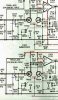
I found a Schematic of the Denon online but it doesn't make me any wiser.
I wonder if someone would be so kind to have a look at it and see if they can find out what the capacitance is.
The schematic can be fount here: Link
Thank you very much.
I'm new to this forum and I'd like to ask for some help concerning my Audio-Technica LP120X.
I own a Denon PMA-800ne amp with build-in preamp for MM and MC cartridges. Now I'de like to figure out what the preamp capacitance is, to see if it meets the recommended load capacitance of my AT-VM95E cartridge (100-200pF).
I found a Schematic of the Denon online but it doesn't make me any wiser.
I wonder if someone would be so kind to have a look at it and see if they can find out what the capacitance is.
The schematic can be fount here: Link
Thank you very much.