• The move to the new server is done. There are some software and database maintenance updates in process. This has us passing the hat around to help out. We appreciate any donations. Seriously, even a dollar helps. The payment page may be found here - https://www.audiokarma.org/support.html

Schematic Review Please - Dynaco inspired 807

dwolek

New Member
I have a VTA octal board I want to use so thought it might be a little different to build an 807 with OD3 tubes to regulate the screen voltage. Can the group please have a look at the schematic below and flag any errors or offer up some performance improvement ideas - particularly with the screen regulation circuit. Much appreciated.

Untitled.png
 
Register to hide this ad
100K from feedback to ground at the input tube seems impossibly high for a total cathode resistor value. If thats supposed to be 100 ohms, thats going to make for not much feedback with a 6.8K resistor.

whats the input tube? 4mA seems about right for a 6SN7 but I suspect thats not really enough gain to also have any sort of appreciable feedback level. 6SL7 may be a better fit here, but the plate and cathode resistors won't be right for that.

an 807 does work just fine in UL mode, so you can make use of that if your transformers have UL taps if you don't feel like messing with the screen reg setup. Also generally speaking you don't want gas regs in parallel since they rarely fire at exactly the same voltage. It makes for weird current sharing. If the mosfet is doing the heavy lifting as a pass regulator, there isn't a need for the gas reg to handle much current anyway. For 300v out, a pair of OD3 in series with no zener would be the way to go. May want to do a high value resistor across each to make sure they share current evenly too, 470K ought to get it done. Add an 0.1uF to ground from the mosfet gate to dump any HF trash they introduce.
 
Thanks gadget. Yes, this is a 6sn7 octal board. As for the OD3 circuit, these should be shown in series - good catch. Good suggestion for the balancing resistors. As for the MOSFET, this is indeed being used as the pass regulator with OD3 providing the reference. I'm just not comfortable that I've drawn it correctly to use the MOSFET as a source follower. I understand I could go UL or just use the OD3 for regulation, but the MOSFET offers several advantages so would like to utilize it.
 
yea missed that. 470K I could believe though.

the 100uF next to the screen reg is sort of extra too now that I'm looking at that part of the supply. Its in parallel with the series 220uF caps. Makes for effectively 210uF, which is fine, but its a 500v cap in parallel with effectively a 700v cap. Can't hit that with more than 500v safely, and that sort of defeats the purpose of having the two in series to get a 700v cap. Not going to hurt anything but you could just get the same thing done with a single 220uF 500v cap.


something else I just noticed, the coupling cap to the inverter is at a tap point of two 30K resistors in series that make up the plate resistor on the input tube. Thats going to throw away 50% of the signal available at that first tube. Not really a good reason to do that.

 
mildly surprised they have a coupling cap there. I'd have figured it would just be direct coupled. Unless the CCS doesn't want to have that much voltage dropped across it.
 
yea missed that. 470K I could believe though.

the 100uF next to the screen reg is sort of extra too now that I'm looking at that part of the supply. Its in parallel with the series 220uF caps. Makes for effectively 210uF, which is fine, but its a 500v cap in parallel with effectively a 700v cap. Can't hit that with more than 500v safely, and that sort of defeats the purpose of having the two in series to get a 700v cap. Not going to hurt anything but you could just get the same thing done with a single 220uF 500v cap.


something else I just noticed, the coupling cap to the inverter is at a tap point of two 30K resistors in series that make up the plate resistor on the input tube. Thats going to throw away 50% of the signal available at that first tube. Not really a good reason to do that.
The 470K I used because they are rated at 700v and because I had them - I understand that balancing wont be as "good" and longer bleed time. I'll change them out with suitably rated 220k's. I'm not clear on the regulator cap placement though - should this be in parallel with the bleeder resistor?
 
The schematic calls for 470 ohms, thats the problem. 470K vs 220K doesn't matter so much but if its 470 ohm it will be very unhappy.


The cap as part of the reg isn't really a placement issue, just that its not needed. Its a 500v cap in parallel with 700v caps, so that circuit is now limited to 500v max. Electrically speaking you could get this done with a single 220uf 500v cap where its currently using 3 caps and 2 resistors to end up with a network good for 210uF at 500v. If its running at 490v steady-state, I'd want higher than 500v here though, any sort of fluctuation has the potential to exceed the cap rating. Losing the 500v cap entirely and just using the the pair of 350v in series would do just fine.
 
And they have a measurable current drift with temperature. But it can be readily compensated.
View attachment 3865769
LM334’s other job is as temperature sensor, so it can only be a CCS of known current at a set temperature. But I wonder how much of an issue current drift is in practice, once the temperature below the VTA PCB has stabilized to operational conditions. With hundreds and perhaps thousands of happy users I suspect the VTA boards function well enough. But when are we satisfied with well-enough?

I’m struggling with that question right now since I have two VTA-70 board being populated. One is an octal, the second a noval. On the octal I installed small heathsinks on the LM334s, thinking the extra thermal mass might help even out variations in temperature, and defuse some of the heat generated in the LM334. I am actually more concerned about using the LM334 at 8.2 ma, close to the upper edge of its current range (10 ma max). I am aware of the nifty little PCB vended by Audiolamp.eu but with shipment they are ~$53 per pair plus an unknown tariff. Definitely worth it to some, but I’m cheap.

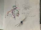
On the noval board I’m going to temp. stabilize the LM334 as indicated in the datasheet (page 8) by adding the diode/resistor. My first attempt at building that looks like the picture below:

Apologies to @dwolek if this is too much of a diversion, but I thought you might appreciate these consideration w.r.t. LM334 usage.
 

Attachments

  • image.jpg
    image.jpg
    329.2 KB · Views: 4
recent thing I was introduced to are the IXYS CCS devices which have internal temperature compensation. Possibly an alternate path to consider here.

IXCP10M45S

4 bucks, though it does drop more voltage
 
Something like that would be nice.

However, in this case of the VTA board the LTP cathodes sit at 10.5 V. Google thinks: “The minimum operating voltage between the anode and cathode of a IXCP10M45S for stable operation as CCS is 20 Vdc.”

If one is energetic and knowledgeable enough the board could be redesigned to increase the LTP tail voltage drop so that a IXCP10M45S could be used (and do away with the coupling capacitor that irked Gadget in post #11), but I’m not.
 
Last edited:
something else I just noticed, the coupling cap to the inverter is at a tap point of two 30K resistors in series that make up the plate resistor on the input tube. Thats going to throw away 50% of the signal available at that first tube. Not really a good reason to do that.
The way I understand it the top 30k resistor and the associated HV capacitor is part of the power supply and set up the correct plate voltage across the remaining resistor for the desired operating conditions on the voltage amplifier triode. Is that not correct?
 
Back
Top Bottom