• The move to the new server is done. There are some software and database maintenance updates in process. This has us passing the hat around to help out. We appreciate any donations. Seriously, even a dollar helps. The payment page may be found here - https://www.audiokarma.org/support.html

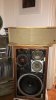
Scored some Janszen 1-30's

nickdinatale

Active Member
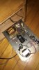
Just picked these up today. Unfortunately they came untested, so I was a bit stressed out by the time I was hooking them up. Fortunately one fired right up and sounds wonderful (my first experience with electrostatics). The other makes no sound when attached and plugged in.

Wondering where I should go from here? There doesn't seem to be a ton of info on restorations available, but it is pretty cool that sending them back to Janszen is an option. Either way, here are some photos for anybody interested in taking a look.
 

Attachments

  • IMG_5395.JPG
    IMG_5395.JPG
    51.1 KB · Views: 151
  • IMG_5396.JPG
    IMG_5396.JPG
    46.7 KB · Views: 147
  • IMG_5393.JPG
    IMG_5393.JPG
    42.4 KB · Views: 156
Register to hide this ad
I've got a pair of JansZen Z-600's that need restoration. New caps for the tweeters and the power supply. New resistors installed. Mine have a selenium rectifier in the power supply, it needs to be replaced with a diode. Just like working on vintage tube powered equipment. Once the power supply is rebuilt, all should be FINE.

Biggles
 
I've got a pair of JansZen Z-600's that need restoration. New caps for the tweeters and the power supply. New resistors installed. Mine have a selenium rectifier in the power supply, it needs to be replaced with a diode. Just like working on vintage tube powered equipment. Once the power supply is rebuilt, all should be FINE.

Biggles
Thank you! That's great to hear. I guess I'll start there and update the thread once I know more! Good luck with the Z-600's as well - I'd love to hear a pair of them at some point but I've yet to come across any.
 
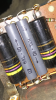
Could anyone answer what these "D7 HXL 40" are? I'm assuming they're some sort of diode, but I'm not sure what to use as a replacement. This particular 1-30 is serial no. 4088, which isn't covered by the available schematics. Pretty much just matching components to make an order of new stuff to put in this. Any help is much appreciated!
IMG_5403-1.PNG
 
So! Recapped both, replaced those diodes, and replaced the majority of resistors. Still no sound out of the one that wasn't working before. The operable one sounds great though.

Does anyone have any recommendations as to where to go from here?
 
I had the Radio Shack Electrostat version of that set up (thought one speaker was a 2, not 2a, so no dome). Sounded really good to my 18 year old ears. I fear that now I couldn't even hear the electrostatics.
 
So! Recapped both, replaced those diodes, and replaced the majority of resistors. Still no sound out of the one that wasn't working before. The operable one sounds great though.

Does anyone have any recommendations as to where to go from here?

How did you replace the diodes since your previous post stated you did not know what to replace them with?
 
The gray diodes are likely selenium stacks, similar to what was used for a television's high-voltage rectifier for the CRT. Series devices — lower-voltage capacitors and diodes are commonly series-wired to permit use high-voltage circuits — reduce the voltage across each device, albeit at the risk of catastrophic failure if one of the series devices fails and the voltage increases beyond the breakdown voltage of the remaining devices.

I don't know how recent your schematic is; mine are dated May 1970 and April 1960. I quickly examined the two and did not observe any differences.

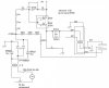
I previously posted the 1960 version that I somewhere found. Here is the link, in case that is helpful:
 
Does anyone know if this Janszen 1-30 is safe to run full range without fear of low frequencies harming it?
In other words, does it filter out low frequencies?
 
I don't know how recent your schematic is; mine are dated May 1970 and April 1960. I quickly examined the two and did not observe any differences.

I previously posted the 1960 version that I somewhere found. Here is the link, in case that is helpful:
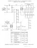
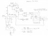
I'd seen yours before, though I hadn't saved it or compared it to the
ones I have. There are apparently at least two other versions, up to
about serial 5759 and from 5760 on. The latter is the only one I
(intially) could find. I have an earlier pair that didn't match, so I wrote
Janzsen and got a hand-drawn schematic for serial 5121. (They
don't have much on these, obviously). So here's my effort at
cleaning it up.

1-30 to SN 5759.jpg

1-30 SN 5760 and above.jpg
 
Nice work on the schematic!

Can you also post the original you received from JansZen for my collection?

You might also post your redrawn version as a full-resolution (300 DPI) PDF on an 8.5 × 11 sheet to permit printing out for inclusion with the original documentation. (Hint, Hint.)
 
The 5759 schemo doesn't show a value for the inductor,
but I have a DATS v3 from Parts-Express, which is capable
of determining it. so I'm just reminding myself here to dig
out the hardware and get a number. Real soon now.
 
The frequency response was listed in Allied's1958 catalog as 500 Hz to > 30,000 Hz, perfect for the AR-1. Component values for that claim are not specified, but would match your schematic. So 50 µF and an unknown inductor, which would be ≈ 2 mH to obtain 500 Hz. The 1.5 mH used in later units would be 581 Hz which doesn't match that claimed specification.

The April 1960 schematic for serials > 8,253 combines 40 µF with 1.5 mH and 1 Ω, yielding 650 Hz. Later units specified a 5 Ω resistor for @ 6 dB / Octave, and directed to remove the resistor to obtain 12 dB / Octave.

This suggests the frequency was ≈ 500 Hz in 1958 which then increased to ≈ 650 Hz after 1960.

I have a undated manual on blue paper for the Model 1-30 and Model 65 specifying a new filter for "peaky woofers" at 800 Hz with 25 µF, 1.5 mH, and a 1 Ω resistor, which actually yields 821 Hz, close enough to 800 Hz to call it even.

Yet, given all of this, the 1.5 mH value consistently shows up in the JansZen schematics and text, I'd speculate that this is the value in your older unit. Seems to be the standard inductor.
 
Last edited:
Back
Top Bottom