• Please note that Audiokarma will be offline briefly for updates early on Monday morning, September 28th.

Scott 222C

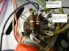
Not only has he lifted the cathodes 10 ohms off ground but he has also lifted the 220K resistors 10 ohms off ground, as well. That's my point.

It may not make much difference. But, along with the cathodes, his 220K's are now 10 ohms further from ground than they were. That's what I'm trying to say here.
 
Last edited:
well you have to realize that its hard to see what is connected to what from the picture. If the cathodes are not connected to ground at all then the amp will not work at all. Install new 220K resistors from the pin 8 junction to the ground connection and then connect a 10 ohm resistor from each pin 3 to ground. I'd also replace the 330K and 1 K resistors while I was at it. They will have been heated up a few times by the time you get this fixed so replacement is wise. Use Carbon film resistors!!!
 
I fully agree. So, see if you agree with what I propose:

7189.JPG

This will put the 220K's back on ground while continuing to 'float' the cathodes by 10 ohms for biasing purposes.
 
Last edited:
Nope I wouldn't do it that way. Pin 4 is the heater voltage although Scott did ground it so I guess it would work. I'd just add a couple terminal strips.
 
Agreed. Since pin 4 (one side of the 6.3v filament supply) IS grounded (as seen in the photo) moving all connections from pin 3 over to pin 4 changes nothing electrically- only visually.

As you pointed out, terminal strips should be utilized because there would likely be six or seven wires on pin 4 after surgery. Phillip already has terminal strips in place.

So, to quickly summarize the process- One of the procedures would be to remove most everything from his new terminal strips. Another procedure would be steps 1 and 2 in my photo a couple of posts back. Finally, during all this, replace the resistors you recommend he change, Craig. Because, indeed, the original resistors are going to be stressed during this operation.

You with us on this, Phillip?
 
Just got back in Canada not too long ago--I'll flip my amp and take a peek at what's what. Thanks for the suggestions!
 
Welcome home, fragger!

Craig pointed out that...

--snip-- a 10 Ohm resistor from ground to each cathode would make measuring the bias much easier. But with a 222C it means moving many resistors that connect to the cathode pin on the tube sockets for the ground point.

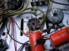
Since I am preparing to do the same operation that you did (less the tip jacks) I was looking closely at your photos. It would appear that the 10 ohm resistors were not "by themselves" on the cathodes.

If I am correct, can you comment on why you placed the 10 ohm resistors where you did?

Brian
 
Shouldn't the cathode resistors have been installed here, instead?:

Schematicexcerpt10Rtypicalrevised.jpg

Now that I'm all woken up, I remember thinking that that's exactly as it was done (albeit in a more roundabout, messy way), with the jack tapped at the cathode/resistor connection point.

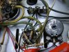
I desoldered everything else that was on the cathode pin, lifted it, soldered on a wire from the the cathode pin and ran it to the terminal strip, and soldered a wire to whatever I lifted off and ran it to a star-ground point on the terminal strip.

This picture from post 176 shows it in detail, smack in the centre of the frame:

2011-01-06-144320_sm.jpg

As you can see the wire from the resistor that was removed does right to the star-ground while the wire from the socket runs off to a resistor. Hope that clears that up! It's not the cleanest job I've ever done, so I'll rework it now that I'm back home and school's out for the summer. Thanks for keeping me on my toes, Blast. :)


Install new 220K resistors from the pin 8 junction to the ground connection and then connect a 10 ohm resistor from each pin 3 to ground. I'd also replace the 330K and 1 K resistors while I was at it. They will have been heated up a few times by the time you get this fixed so replacement is wise. Use Carbon film resistors!!!

I'll get right on it! Thanks Craig, good to have you back :)
 
Last edited:
Done. I found out I had only been running about 9ma of current on each EL84M I added a bias trim pot (just one, though) and set the current up into the low 20's. Great thread Phillip and Craig! :yes:

20110615 HH Scott 222C adding 10 ohm bias check resistors 7 Copy.JPG
 
Last edited:
Thanks, P. Did you ever figure out what the effects of lifting the 220K's off ground by 10 ohms were? Probably nothing at all- Craig hasn't commented on it.

220K. I keep calling them that, you know. But, our amps actually use 270K- which is what I replaced with. (220K is what the schematic I have says.)

Brian
 
Last edited:
Thanks, P. Did you ever figure out what the effects of lifting the 220K's off ground by 10 ohms were? Probably nothing at all- Craig hasn't commented on it.

220K. I keep calling them that, you know. But, our amps actually use 270K- which is what I replaced with. (220K is what the schematic I have says.)

Brian

I'm not sure what the effects might be, sadly. I've got them installed as such:

Schematicexcerpt10Rtypicalrevised.jpg

They only ever meet at the grounding point, so one shouldn't influence the other.
 
You don't have two resistors connected to pin 3?

I think you missed what I wrote in post #289:

Now that I'm all woken up, I remember thinking that that's exactly as it was done (albeit in a more roundabout, messy way), with the jack tapped at the cathode/resistor connection point.

I desoldered everything else that was on the cathode pin, lifted it, soldered on a wire from the the cathode pin and ran it to the terminal strip, and soldered a wire to whatever I lifted off and ran it to a star-ground point on the terminal strip.

This picture from post 176 shows it in detail, smack in the centre of the frame:

2011-01-06-144320_sm.jpg

As you can see the wire from the resistor that was removed does right to the star-ground while the wire from the socket runs off to a resistor. Hope that clears that up! It's not the cleanest job I've ever done, so I'll rework it now that I'm back home and school's out for the summer. Thanks for keeping me on my toes, Blast. :)
 
I know this is a necropost, but I read all 20 pages this evening and this was a wonderful way to spend a night. What a great journey! From the sellers crappy iPhone pics to the end. Great job Fragger! What an inspiration!
 
Sorry to resurrect this old thread again, but as it's a very helpful one, I just wondered if there is any way of restoring all or some of the lost photos? I think these went with the software upgrade.
 
Back
Top Bottom