• The move to the new server is done. There are some software and database maintenance updates in process. This has us passing the hat around to help out. We appreciate any donations. Seriously, even a dollar helps. The payment page may be found here - https://www.audiokarma.org/support.html

Scott 299 A or B restoration

Thocom

AK Subscriber
Subscriber
Hi all,

Ive decided to take on the challenge of restoring this piece. This will be the most complicated piece i have done to date. Ive restored a few dozen tube radios, consoles in the past, including a Fisher tube amp and feel i can get through this (with the help of you fine people). This is in beautiful, untouched, original condition and i don't want to do any damage to it so i will be taking it slooow.

First question:

1. What is it? lol, I think its a Scott 299B since it has the center channel jacks?

2. Serial number is 14001, does the SN have any info in it that can help?

3. I haven't powered it up, I am going to put some garbage tubes in it, and bring up on a variac once i get the new GZ34 rectifier. Good idea? or should i change out anything first? Maybe do the PS and coupling caps.

4. There has been some mention of the selenium rectifier, replacing with a Rat Shack part, is that still available or should i look for an alternative?

Here are some pics that should not be upside down :)

attachment.php


attachment.php


thanks,


Tom
 

Attachments

  • IMG_2454.jpg
    IMG_2454.jpg
    51.3 KB · Views: 391
  • IMG_2456.jpg
    IMG_2456.jpg
    78.3 KB · Views: 101
  • IMG_2457.jpg
    IMG_2457.jpg
    70.7 KB · Views: 104
  • IMG_2473.jpg
    IMG_2473.jpg
    49.2 KB · Views: 96
  • IMG_2475.jpg
    IMG_2475.jpg
    71.7 KB · Views: 409
Register to hide this ad
wooohooo, i actually figured out how to post pics directly into the post!!


attachment.php
 

Attachments

  • IMG_2479.jpg
    IMG_2479.jpg
    112.4 KB · Views: 113
  • IMG_2474.jpg
    IMG_2474.jpg
    57.6 KB · Views: 78
  • IMG_2477.jpg
    IMG_2477.jpg
    72.7 KB · Views: 85
  • IMG_2478.jpg
    IMG_2478.jpg
    71.9 KB · Views: 373
What you have is the second generation 299. The first generation 299 would have the output tubes along the left side of the chassis (looking from the front).

The 299B would be marked as such. The difference is not much. Your challenge will be the filter capacitors since this amplifier is about 54 years old. I would change them first. You have many options. What I have done is to either replace the existing ones with JJ and clamps which look different but work well. As for the bias bridge, the Siemens Selenium rectifier, that can be replaced with a silicon bridge which is even available from Radio Shack. You may need to replace the first resistor after the bridge, I think it is an 18Ω 1-Watt with something like a 22Ω or 33Ω 5-Watt resistor. The reason is that silicon is more efficient than selenium and the voltage may be too high. This negative supply is used for bias on the output tubes as well as for DC filament voltage for the 12AX7 tubes which the filaments are wired in series.

Note that the capacitor that follows that bridge is unique in that the can is positive, not negative. There is scant room under a Scott amplifier so you may have to become creative. I opt to open up the old cans and stuff them with new capacitors. Looks original and fits the same space.

I would also replace all of the paper capacitors, the Pyramid brown ones with new film capacitors, especially the ones that feed the grids of the 7189 output tubes. You will get many opinions about what type of capacitor to use. Freedom of choice of course. For me, I don't subscribe to boutique coupling capacitors, opting for the "Orange Drops" or yellow "Lemon Drop" ones.

Here is the bottom of my first generation 299. (I still want to replace those .02µFD disc capacitors, just have not gotten around to it.)

299-Bottom.jpg


Nice amplifier! I have an first generation that I have rebuilt and a second generation that is still in queue. Keep us posted, and ask away.
 
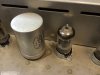
I just noticed that the 5AR4/GZ34 in your amplifier is most likely bad; has gone to air. The indication is the white color. That is a bummer because they have become very expensive. You could look for a good used Mullard or GE or buy a Sovtek (Russian made) for that. The Sovtek will be about $12-14 and the Mullard will often be ~$50.00.

If you compare my first generation 299 to your second generation, the tube layout is different and also the location of the silicon bridge is different. Your second generation 299 has the bridge in essentially the same location as the 299B.
 
As usual, kvflyer nailed it. It's a 299 sec gen often referred to as a 299(A).

When restoring these old amps, I always like to get them working before I start the proper restore. It makes it much easier to troubleshoot as you go along. I restore in small sections and test after each section. If a cap gets wired backwards for instance, you know it's one of the last 3 or 4 you put in rather than something somewhere in the whole amp.

Here's the link to my own 299(A) restore: http://www.audiokarma.org/forums/showthread.php?t=490854

Good Luck!
 
It is not a "B". I had one. B has bias setting pots and a bias setting shorting jumper
adjacent to the pwr trans.

Very Nice looking 299A.
 
For whatever it may be worth, the $16 Sovtek GZ34/5AR4 tubes I got from Jim McShane are holding up fine in my Bogen amp. I'm using FT can caps in that too, also from him, reasonably priced, and they work. It does need the clamps, but the clamp mounting holes match up to the original rivet holes so it was a simple matter of drilling out the rivets and replacing with small machine screws to install them.
 
As usual, kvflyer nailed it. It's a 299 sec gen often referred to as a 299(A).

When restoring these old amps, I always like to get them working before I start the proper restore. It makes it much easier to troubleshoot as you go along. I restore in small sections and test after each section. If a cap gets wired backwards for instance, you know it's one of the last 3 or 4 you put in rather than something somewhere in the whole amp.

Here's the link to my own 299(A) restore: http://www.audiokarma.org/forums/showthread.php?t=490854

Good Luck!

I like the way you think. One small part at a time, testing in between. That's how I like to work as well.
I will probably just buy the cans, or some cans, some stuffing. We will see.

Yes, that 5AR4 is toast. I knew that before I bought it. Considering the glass comes off the tube completely :( the rest of the tubes tested very good though :)
Thanks all for setting me straight on the model number. I had not realized that there were different layouts of the same unit. The toasted tube was a Genelex Gold Lion, double mica I think.
I will find a Mullard for it when it's healthy, but until then I will pick up a JJ from Guitar Center for $13.00.

-Tom
 
Any suggestions for the .001 2500V cap from pin 7 of V10 and V5 (power tubes)?

...

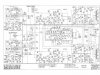
Good question. The schematic that is on the HH Scott site is a Howard W Sams copy, not a Scott schematic. I doesn't appear to have that capacitor in the circuit. I have that entire Sams and the picture of the amplifier in the Sams is of the early generation. So, originally, they did not use it.

http://hhscott.com/pdf/sd/299A_3_4s.JPG

Long story short, do NOT use a capacitor of lesser voltage. That capacitor is used to suppress spikes hitting the primary of the output transformer. Things like momentary disconnect of the speakers will cause the signal to be reflected back from the secondary of the (expensive) output transformers and could do damage to the primary or cause an arc in the output tube socket.

I have replaced two output tube sockets (not in HH Scott) in amplifiers which had burned tube sockets. When the arc occurs, it leaves a carbon track and erodes away the material. There is no "cleaning" of the socket, replacement is the only option.

So, since most capacitor testers will not test up to 2500VDC, you don't have the option to "test" those capacitors. If you can't find them immediately, you could "temporarily" remove them. But I would not.

And importantly as "njcanuck" has pointed out, get it working first. Go carefully. The important things are the filters, bias and coupling to the 7189 tubes. I did replace all of the tubular capacitor on my tone controls and selector switches. That may be overkill because these locations see very, very little voltage. If those capacitors are leaky, it will just be like bridging a resistor (of the leakage value) across or parallel to the capacitor. Working around the selector switch is very delicate and tedious. Permanent damage can easily happen.

Many of my friends clip the existing lead of the component and just use a "J" hook in the wires of the existing component and the new capacitor. That is an acceptable practice. But me being my anal self, I insist on removing the old component completely and installing the new one just as the old one was installed. That is just me.

Here is my selector switch on the 299. Mind you, at this time, I was using "Orange Drops". I didn't have any of those yellow capacitors yet. You can see how tedious it is. Not also that you don't have to replace those brown silver mica capacitors. They will be just fine.

Interesting to note that I did change the plate resistors in the past on the 12AX7 tubes, arbitrarily. I don't do that anymore. I have not had any problems with the original 100K ohm 1-watt resistors that Scott used. However, if the amplifier was driven into the ground, "Your mileage may vary" as they say. Changing them would be way down on the list after getting it up and running.

You have a very, very nice amplifier. Please take your time and proceed slowly. You will be easily rewarded with a smooth, clean sound at about 17 Watts Per Channel RMS.

(I don't have access to my Scott amplifiers right this minute. But starting tomorrow, I will be with them for two weeks. I would be happy to take pictures, examine or whatever to help you with questions.)

Selector:

Selector.jpg


And a tone control:

Tone.jpg

Thanks much! A couple of photos of your work would help greatly.

I replace caps the same way, its not too difficult with some wicky wire to remove the whole lead and re-install from point to point. sometimes a bit tedious if there are a lot of other connections from the same point, but this Scott is laid out in a way that there isn't too much of that. Some of those caps on the POTS are going to be fun to try and change! definitely down on the list..

This is my winter project and expect it will take me some time to finish, that's ok, this is all part of the fun of this hobby. 33% finding the gear, 33% working on the gear, and 33% enjoying it. Yeah, there's that 1% left over, that's for sourcing the parts :)
I was just taking an inventory of what I need to purchase and what I have on hand and saw this 2500V cap and figured I'd ask what other people have used.
Still on the fence if I am going to replace the cans or stuff them, the $$ are starting to add up, but I kinda like the Scott logo on the current cans so I am leaning toward stuffing them.

thanks again,
Tom
 
I was just taking an inventory of what I need to purchase and what I have on hand and saw this 2500V cap and figured I'd ask what other people have used.

Tom

I (and others) used sprague orange drops .001 @ 1600V, available from Mouser.

Also, there is a proper HH Scott schematic in the AK database.
 
I (and others) used sprague orange drops .001 @ 1600V, available from Mouser.

Also, there is a proper HH Scott schematic in the AK database.

Is the one I posted a picture of the wrong one? It calls out this .001 cap. Was there another version that had it?
 
Sorry, that is the correct schematic. I thought you were using the SAMs version.

I don't personally have a copy of the Scott schematic for a 299, only the Sams version. And looking at the Sams, the early model is obviously what Sams used. Glad that this site has the other version.

Thanks!
 
If you look on the lower left hand side of that schematic, you can see the documented engineering change order when that cap was added. I used a 5kv ceramic cap when I did my 299a ages ago. Worked fine. Mouser sells these.
 
I'm stuffing the cans and in the process of buying radial caps, two of the cans call out 20/30 uF 475V.

Mouser only sells values up to 450V, anyone know a source for these caps?
 

Attachments

  • image.jpg
    image.jpg
    60.7 KB · Views: 36
Just Radios has them. I didn't find the dimensions of the capacitors but I am sure that an email to the Cantelons in Canada would get your answer.

http://www.justradios.com/cart.html

As an alternative, you can put electrolytic capacitors in series. For instance, you could put two 350 VDC caps in series and it would yield 700 WVDC but at half of the value. i.e. two 40 µFD @ 350 VDC in series would yield 20 µFD @ 700 VDC. You must use like values, brands and vintage to be safe. There is an ongoing debate as to whether you need a stabilizing resistor over each of the capacitors. And of course, size of the can being stuffed may be the issue!

You are right however, finding capacitors over 450 VDC is the challenge!

I see in another thread on this unit, that a 450V was used in place of the 475V. I'm unsure if I should do this. It worked out for them, but with my luck a catastrophic event will take place. :)

Thanks for the link, I just ordered the 500V, although they are axials, I should be able to fit them with some creative shrink wrapping.

-Tom
 
Last edited:
Back
Top Bottom