• The move to the new server is done. There are some software and database maintenance updates in process. This has us passing the hat around to help out. We appreciate any donations. Seriously, even a dollar helps. The payment page may be found here - https://www.audiokarma.org/support.html

Scott 340B

jeffersondc

New Member
Hi!

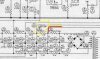
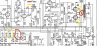
I have a Scott 340B receiver which has Plate voltage of 450V, screen 430v.

i would like to drop the screen to 350v from 430v. Based on the attached schematic, i would need to replace R405 330/2W with a 5k/5W resistor to let 20ma (approx) pass through.

Are my calculations correct? 450v-350v=100v. 100v/20ma (for 4 tubes) = 5,000 ohms.
wattage rating: 100v x 20ma = 2W
I have a 5K/5W resistor i can use.

Would there be negative effects upstream or downstream with this change i'm considering? (Scott engineers chose these circuit values based on their calculations).

thank you all for your replies
528A83FE-D668-4AB3-BD8A-C01C3999FF14.jpeg 27297296-D6A9-4B24-8F7E-B5192FFF9571.jpeg C86FB8CD-EE7F-4493-94BC-44448F09F9B1.jpeg
 
Register to hide this ad
Any reason for doing this? Adding a bunch of resistance in the power supply will severely affect regulation and degrade performance. Also depending on the particulars of the output transformers, dropping the screen voltage might cause a mismatch between the output tubes and the trafo. I'm not at all experienced with Scott stuff so I don't know what those have as far as output trafo impedance.

You'd be much better off using a regulator of some form to drop it without a bunch of extra resistance. Sounds like a good application of an EFB setup. A bunch of resistance ahead of the screen will cause serious sag under load. It will also cause the stages downstream of the screen supply to dip at higher output. Lower screen voltage would drop power supply load considerably so the B+ will go up unless you compensate with less grid supply too.
 
If you lower your AC line voltage, it will lower everything and if appropriate, extend the life of the 340B, if that is what you are looking for. One of the easiest ways to do that is with a bucking transformer. Filament transformer of 6.3 or 12.6 volts connected as bucking will do it the most efficiently without much loss or energy turned into heat as resistors do.
 
Is this related to saving the 7591 output tubes?
yes :) the tubes are US made coin base 7591A (according to their markings). Don't know how much life they still have in them. Seeing the data sheets made me wonder if the 340B operating points were designed to extract the maximum output from them (which I don't need).
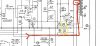
I would prefer to set their operating points according to the datasheets.
 
Last edited:
If you lower your AC line voltage, it will lower everything and if appropriate, extend the life of the 340B, if that is what you are looking for. One of the easiest ways to do that is with a bucking transformer. Filament transformer of 6.3 or 12.6 volts connected as bucking will do it the most efficiently without much loss or energy turned into heat as resistors do.

That's a good idea.It's just that the operating voltages downstream (from the driver tube to the preamp stages) would be affected as well. I would like to limit any changes to the output stage only. If that's possible :)
 
Any reason for doing this? Adding a bunch of resistance in the power supply will severely affect regulation and degrade performance. Also depending on the particulars of the output transformers, dropping the screen voltage might cause a mismatch between the output tubes and the trafo. I'm not at all experienced with Scott stuff so I don't know what those have as far as output trafo impedance.

You'd be much better off using a regulator of some form to drop it without a bunch of extra resistance. Sounds like a good application of an EFB setup. A bunch of resistance ahead of the screen will cause serious sag under load. It will also cause the stages downstream of the screen supply to dip at higher output. Lower screen voltage would drop power supply load considerably so the B+ will go up unless you compensate with less grid supply too.

I'm interested in that EFB. has something similar been applied to the 340B?
 
looking at other scott 7591 schematics. it appears they derive screen voltages in different ways. The LK72 A through a voltage divider (R213 and R215) from the B+ line (red)
23FCB590-8654-48ED-B84E-16494D98ED3A.jpeg

and the LK72B direct from a tap on the HV (B+)B125D914-7A23-4F7F-A553-318C42922DC6.jpeg

the 340B adds a series resistor for the screen supply
 
I'm interested in that EFB. has something similar been applied to the 340B?

Not sure about the 340B specifically but you might get some inspiration here

https://www.audiokarma.org/forums/index.php?threads/modifying-the-fisher-400-with-efb.509090/

Just bear in mind that the reason for changing the screen voltage on the 400 was a mismatch in the output transformers. I don't know if thats the case on the Scott.

Honestly I don't think dropping the screen voltage is going to do all that much for extending the life of the tubes. You'd get more out of knowing what the idle current is and making sure its not excessive. EFB on both the screen and grid could result in an operating point that is lower than the stock design though, and that will extend life. Cuts distortion too, win all around.
 
Back
Top Bottom