• The move to the new server is done. There are some software and database maintenance updates in process. This has us passing the hat around to help out. We appreciate any donations. Seriously, even a dollar helps. The payment page may be found here - https://www.audiokarma.org/support.html

Scott amp 299-D motorboating

charlesaudio

New Member
I have a Scott 299-D that has a serious oscillation or motorboating issue, (almost like a low frequency feedback)
when it's in phono position with the loudness at around 2-3 o'clock with or
without a tuntable. I can see the amplifier have seen some restoration : a
lot of coupling capacitor and resistor have been replaced but not the ones
into the supply section. The rumble filter has been bypassed and the
scratch filter has been modded to be always ON. I've connected back the rumble filter and it's
better, there is no more motorboating with headphones, only with the
speaker now. If I cut the bass it also starts to oscillate later, when the loudness pot is near the max.

The amplifier doesn't hum particularly and works ok otherwise. Doesn't meet
the original specs distorsion-wise but it's probably related to be all original tubed.

Any advice would be appreciated

Thanks
 
Register to hide this ad
Check with the schematic that all replaced caps are the original values. And i mean coupling caps and
every one in the signal path. Also check that feedback network is in accordiance with schematics.
 
The type of oscillation you describe is very likely due to a failed power supply cap -- likely the one that serves the phono preamp stages, but it could also be the one for the tone/line stages, or the one(s) serving the phase inverter tubes -- or any combination of them. In the early stages of an amplifier, these caps to little if any actual filtering. Rather, they decouple the various stages from each other, so they won't feedback between themselves through the power supply connections. It is customary to feed no more than two cascaded stages from a single power supply tap (feeding both channels), although sometimes three stages are OK as long as the overall gain of those stages is fairly low. However, if the power supply cap goes south with even just two stages from one tap, all manner of oscillation and weirdness can happen due to unintended coupling. You say that the power supply caps have not been replaced. Doing so will likely solve your problem.

I hope this helps!

Dave
 
Thank you gentlemen. I will confirm the partial restoration followed the schematic parts value and I'll recheck or replace the filter caps. I've actually measured them and they were all within their specs. Some capacitance were even 40% higher...

I'll keep you posted.
 
Vintage can caps that measure notably higher than indicated value is an indication that the cap could likely be starting to loose its form -- another sign they need to be replaced if they will not properly reform.

Dave
 
Its the internal resistance of the cap that matters here, not the particular value. In ancient terms, internal resistance was "Power Factor", in modern terms its ESR. Same difference, basically it just means that the capacitor is less effective than it ought to be, despite whatever value it might happen to measure at. The old power factor scale was measured in percentage, and it actually translated to capacitor efficiency loss.

Of course, low value or open caps also won't decouple the stages either.
 
Ok, in the phase inverter section (6U8) the 4uf/250v electrolytic (C18) has been replaced by a 3.3 film capacitor. Also R25 (8.2k) has been paralled by a 100pf capacitor. I don't see other things that are different from the schematic.

Now for the different stage filtering cap, I can replace them all if my client wants to go ahead - it's few hours of labor- but I'm wondering how a bad cap in phono section could affect the loudness output when turned up. I mean the phono has 44db of gain no matter the loudness pot position and should not be affected by it.

Small video showing the issue : https://drive.google.com/file/d/0BzdmRhYEazSNZ1VCeU1STkJ4SlU/view?usp=sharing
Schematic here.https://drive.google.com/file/d/0BzdmRhYEazSNdVlrZ2FEbi0xTWs/view?usp=sharing
 

Attachments

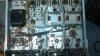
  • 20160711_110954.jpg
    20160711_110954.jpg
    99.5 KB · Views: 21
Last edited:
I think I've found something. According to the manuel, I should get 74V on V3A (V103A) grid #2 (pin 3). I measured 73V on V3A and 42V on V103A. Then I swapped those two tubes (6U8A) and the voltages moved with the tubes, 80V was now on V103A and 42V on V3A.

I don't have 6U8A in stock to test., will order some.
 
Last edited:
Those pentode tubes tend to be fairly variable. Honestly I wouldn't be super concerned with it. Its the screen grid you're measuring, and its probably through a high value resistor. It doesn't take much change to get the voltage to change considerably. if its doing this in both channels, its not a single tube causing you headaches.


Try clipping some caps across the filter caps to see if the problem goes away. That would be a quick and easy method of proving or disproving that idea.
 
I agree high voltage B+ caps are not filtering. The above suggestion will answer the problem . Use some test clip wires to see if this correct.....
 
I agree high voltage B+ caps are not filtering. The above suggestion will answer the problem . Use some test clip wires to see if this correct.....

Yes, as mentioned above, to try this theory, temporary connect another capacitor to the existing one. If the problem "goes away", you know what needs to be replaced.
 
  1. Ok I'll try that. I only have 22uf/450v in stock for the moment. Can it be too much to double up the capacity for the rectifier or the pt?
 
Should be OK, the only one thats particularly cranky is the first cap off the rectifier. It will usually survive brief tests though. Beyond that point, it doesn't matter a whole lot.
 
Cool, first cap I clipped on fixed the issue. It's on phono stage B+. I will propose a complete recap to my client. I'll have to find some multisection capacitor because there is not much space to fit many caps inside. Tubesandmore.com seems a good supplier.

Thank you for your good advices guys.
 
Glad you found it! That cap was the most likely one it would have been, as I stated in my first post. But feedback between amplification stages through the power supply B+ distribution system can produce strange symptoms, which is why the caps at other distribution points were also suggested as a possibility. It clearly shows that power supply caps can fail in multiple ways -- and not just due to the common symptom of developing a high power factor.

Dave
 
Hayseed Hamfest can make you custom fit can caps if needed, should you not feel like re-stuffing them.
 
Authenitic caps on Ebay are good for 550VDC. Not cheap but work good in my Dyna Mk 3's... I'm not fond of Antique Electronic can caps (C E Manufacturing). but JJ's are good (check size & farads)
 
I'm almost done recapping this amp psu (have to find space to replace that 4x100uf cap).

I am tempted to replace the power cord for a three prong. I removed the line filter caps (will replace them with x2/y2 caps). I've tested the amp with a wire clipped from the ground outlet to the chassis and it's cleaner, less buzz/hum. Also without it I measured 45VAC between the outlet ground and amp chassis.

What do you guys think about that ? Sorry, I know it probably have been discussed to death elsewhere.

thanks
 
I have been following this thread. This group has some very sharp cookies, to be sure.

When I purchased my 299D, it was the collective wisdom of the group that helped me get it working properly.
I did notice fairly quickly that the chassis has some hazardous voltage potential. Clipping the disc caps from chassis to line appears to have eliminated this hazard.
Hope it didn't create some other danger.
 
Back
Top Bottom