• The move to the new server is done. There are some software and database maintenance updates in process. This has us passing the hat around to help out. We appreciate any donations. Seriously, even a dollar helps. The payment page may be found here - https://www.audiokarma.org/support.html

Scott LK 72B rebuilding it, as it was never completed... Help.

Bad Tech

New Member
Hello people.

I've reached that stage in my project where I doubt my work, my self and my ability to follow though.
Picked this up for $50.00. In trying to find the proper schematic I realised the builder wasn't focused.
Now I've built a pair of Eico hf30 clones from some Baldwin amps I acquired; survived their spark tests
and I even kept all the smoke in them! So I can read a schematic. Back when I had a Metcal and Pace I
could solder but now I'm using a stained glass soldering iron (don't ask).

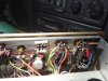
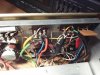
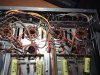
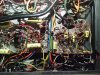
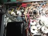
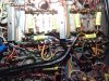
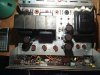
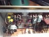
So....if you don't mind, please examine the pictures and let me know f you see something I missed or that doesn't make sense. (I was modding while rebuilding and I stopped working on it about a three years ago!)

Thank you in advance,
Respectfully yours,IMG_20210111_050158.jpg IMG_20210111_050413.jpg IMG_20210111_051806.jpg IMG_20210111_052033.jpg IMG_20210111_052128.jpg IMG_20210111_052140.jpg IMG_20210111_052149.jpg IMG_20210111_052424.jpg IMG_20210111_052441.jpg IMG_20210111_052654.jpg
Todd
 
Register to hide this ad
Welcome,, just curious,, did you get that amp working as Scott intended before adding mods? I usually do, as its harder to troubleshoot,,, and you cant be sure all the parts of the chassis were working as you found it... I'd start by following schem starting with the PS, and making sure everything is connected properly, in working order and reverse the mods made,
Good luck with it,,,
 
Thanks jkaley for the pdf! Wish I'd have had that when I started!
Thanks John for chiming in! I didn't dare put the amp on my variac as it was missing many parts from around a couple of bare sockets.
As for the mods, I didn't do any hot rodding, mainly safety mods such as diodes across the rectifier, a small bump in PS capacitance, etc.
All of that done as I was going through the schematic looking for the original builder's mistakes and omissions.
I did ohm out the transformer windings for whatever that's worth. I was going to test the tubes but my tester had no data for the 7591a {or 7868, 6GM5}
 
If I remember correctly, I stopped at the bias pots. I believe my problem was figuring out adding the cathode sense resistors and tying it together with the bias pots in such a way that if the wiper lifted it would deliver more negative bias shutting off the output tube, or possibly incorporating combination bias into the circuit.
Thoughts? Would additional pictures help?
 
ordered a soldering station, will hit every solder joint! then some measurements and on to the spark test!
 
I'll order parts for the EFB mod but I think I should order some wire and make some room under the chassis first.
It's a rat's nest, for sure!
Need recommendations for bias pots and Teflon wire, anyone?
 
Teflon wire is good for high temperature but it is difficult to strip. My good industrial stripper will often slide on the insulation because the insulation is very slippery. I use regular 22 or 20 AWG plastic coated solid wire for any of my HH Scott amplifiers. Alternatively, I have had a few Scott amps that were basket cases and I have saved the original wiring from them, if it was of substantial length. I will use that first.

Hard to find is wire with stripes. Just about the only place to find that is from a parted-out amplifier if your intent is to be as original as possible. I too have gotten a few Scott-Kit items that had horrible and incomplete assembly over the years. In one case, I actually stripped out what was done and started over again. Resistors were not cut to length, just installed with flying leads.

If this were my amplifier, I would follow the the assembly manual from page one and verify that everything was done correctly. I know that it is difficult, but the manual is correct. As for modifications, I usually leave everything as designed. Why? I am not an engineer and back in the early 60s when these amplifiers were sold, they just worked. I am not into fooling around with the power supply and for sure, do not add capacitance to the filter, especially the first one after the GZ-34. I have not had to use additional diodes on the rectifier. They worked in 1963; they work today as designed. Of course, each of us is entitled to his/her decisions.

Keep in touch, let us know how it goes.
 
Hey Bad Tech, it looks like at least 3 of us on AK are working on Scott 299C, LK72B's at the same time! I've got a LK72B here and from the top the layout is like yours. If you have any specific questions feel free to get at me. I'm glad to help while it's here. PM me if I don't check back in right away. Looks like you're getting good advice so far so best of luck with that "rats nest"! I do NOT envy you! ;) But it's yours and you got a great deal on it. This one is a friends and I guess I actually do envy both of you. Looks like a great unit!
Best of luck!
Mark
 
Hello people.

I've reached that stage in my project where I doubt my work, my self and my ability to follow though.
Picked this up for $50.00. In trying to find the proper schematic I realised the builder wasn't focused.
Now I've built a pair of Eico hf30 clones from some Baldwin amps I acquired; survived their spark tests
and I even kept all the smoke in them! So I can read a schematic. Back when I had a Metcal and Pace I
could solder but now I'm using a stained glass soldering iron (don't ask).

So....if you don't mind, please examine the pictures and let me know f you see something I missed or that doesn't make sense. (I was modding while rebuilding and I stopped working on it about a three years ago!)

Thank you in advance,
Respectfully yours,View attachment 2093752 View attachment 2093753 View attachment 2093754 View attachment 2093755 View attachment 2093756 View attachment 2093757 View attachment 2093758 View attachment 2093759 View attachment 2093760 View attachment 2093761
Todd
I agree down load assembly manual follow it to the letter. Pour over every square inch touch each and every connection with your hand then find it in the manual and verify it. check ever single resistor. Just go ahead and replace all the electrolytics every one of them no exceptions. I dont care what no one tells u about reforming or the greatness of old shitty electrolytics its not true. If they got some kinda werid nostalgia because they bought some when they were 10 and now their
71 because they suck now trust me. if they arent bad they will be. just rip them out and throw them in the garbage and then burn the can to staerlize it and make sure they are dead and gone. They are 2 to 3 dollars to replace with 12000hr rubycons etc. vs 200 or 300+ for transformers and tubes if they can even even be found. Then do the exact same thing to any paper and foil cap or wax cap. This includes the ones that hide in plastic sleeves. Then and only then will u have done your duty in preserving this beautiful amp for future generations to experience and enjoy. If you fail contact me personally and will give 100 dollars for your troubles and bring this lady home to daddy. Where she will have no choice but to sing. lol Good luck sir and God bless u because it takes alot patience.
 
Hello people.

I've reached that stage in my project where I doubt my work, my self and my ability to follow though.
Picked this up for $50.00. In trying to find the proper schematic I realised the builder wasn't focused.
Now I've built a pair of Eico hf30 clones from some Baldwin amps I acquired; survived their spark tests
and I even kept all the smoke in them! So I can read a schematic. Back when I had a Metcal and Pace I
could solder but now I'm using a stained glass soldering iron (don't ask).

So....if you don't mind, please examine the pictures and let me know f you see something I missed or that doesn't make sense. (I was modding while rebuilding and I stopped working on it about a three years ago!)

Thank you in advance,
Respectfully yours,View attachment 2093752 View attachment 2093753 View attachment 2093754 View attachment 2093755 View attachment 2093756 View attachment 2093757 View attachment 2093758 View attachment 2093759 View attachment 2093760 View attachment 2093761
Todd
Oh and buy a Chinese t11 hakko temperature controled knock off and few round wedge tips one or sharps at least of of each. If u can. If u cant just try not not to heat every component too 900f or 500c and youll be ok lol. It will change your life for the better. If your really gonna do work buy vacuum desoldering station it changed my life man it was like the best hundred and fitty dollars i ever spent, and please change those old electrolytics if i can just impart one thing in your mind its that old caps are the worst possible enemy to your **** i hear so many people talking about saving vintage caps let me tell u no. Would u want to jump out of a plain with a vintage parachute. I think not Again flim caps, sprague vitamin anything caps the super high quality vintage caps yes they are special there are no special worth saving electrolytics atoms, trws, mallorys any of them they are all trash. out of the thousands i have tested out of used vintage gear i can count one one hand how many passed a leakage test.
 
Last edited:
Teflon wire is good for high temperature but it is difficult to strip. My good industrial stripper will often slide on the insulation because the insulation is very slippery. I use regular 22 or 20 AWG plastic coated solid wire for any of my HH Scott amplifiers. Alternatively, I have had a few Scott amps that were basket cases and I have saved the original wiring from them, if it was of substantial length. I will use that first.

Hard to find is wire with stripes. Just about the only place to find that is from a parted-out amplifier if your intent is to be as original as possible. I too have gotten a few Scott-Kit items that had horrible and incomplete assembly over the years. In one case, I actually stripped out what was done and started over again. Resistors were not cut to length, just installed with flying leads.

If this were my amplifier, I would follow the the assembly manual from page one and verify that everything was done correctly. I know that it is difficult, but the manual is correct. As for modifications, I usually leave everything as designed. Why? I am not an engineer and back in the early 60s when these amplifiers were sold, they just worked. I am not into fooling around with the power supply and for sure, do not add capacitance to the filter, especially the first one after the GZ-34. I have not had to use additional diodes on the rectifier. They worked in 1963; they work today as designed. Of course, each of us is entitled to his/her decisions.

Keep in touch, let us know how it goes.

Not a Scott 299C or LK-72, but I came upon a Fisher KX200 kit amp (7591's) that was heavily modified to the point that it was difficult to figure out everything that was done to it. I stripped it down to the chassis and started over. All caps, all resistors, all unshielded wires were replaced with new. I had to replace a couple of shielded cables inside and the volume/switch as well. I couldn't find teflon 22awg at 600V solid wire so I went with an assortment (colors) of stranded 22awg 600V teflon wire. In the end the unit was back to what it was meant to be and sounds great. I've since installed the usual safety mods, but I know what I have now and that is gratifying. That kind of start-over is not for everyone, but it is another option for those that dare. Good luck.
 
Hey Bad Tech, it looks like at least 3 of us on AK are working on Scott 299C, LK72B's at the same time! I've got a LK72B here and from the top the layout is like yours. If you have any specific questions feel free to get at me. I'm glad to help while it's here. PM me if I don't check back in right away. Looks like you're getting good advice so far so best of luck with that "rats nest"! I do NOT envy you! ;) But it's yours and you got a great deal on it. This one is a friends and I guess I actually do envy both of you. Looks like a great unit!
Best of luck!
Mark

Thanks Mark!
 
Oh and buy a Chinese t11 hakko temperature controled knock off and few round wedge tips one or sharps at least of of each. If u can. If u cant just try not not to heat every component too 900f or 500c and youll be ok lol. It will change your life for the better. If your really gonna do work buy vacuum desoldering station it changed my life man it was like the best hundred and fitty dollars i ever spent, and please change those old electrolytics if i can just impart one thing in your mind its that old caps are the worst possible enemy to your **** i hear so many people talking about saving vintage caps let me tell u no. Would u want to jump out of a plain with a vintage parachute. I think not Again flim caps, sprague vitamin anything caps the super high quality vintage caps yes they are special there are no special worth saving electrolytics atoms, trws, mallorys any of them they are all trash. out of the thousands i have tested out of used vintage gear i can count one one hand how many passed a leakage test.

Thanks tjasont!
I replaced all but a few electrolytics (missed them when ordering replacements). I have a Pace desoldering station that stopped melting solder... any troubleshooting tips for that one? It's in the attic with fifty spare tips, a few reserve glass pieces, etc.
I picked this up
https://www.amazon.com/Soldering-Ti...ords=soldering+station&qid=1612287938&sr=8-19
 
Not a Scott 299C or LK-72, but I came upon a Fisher KX200 kit amp (7591's) that was heavily modified to the point that it was difficult to figure out everything that was done to it. I stripped it down to the chassis and started over. All caps, all resistors, all unshielded wires were replaced with new. I had to replace a couple of shielded cables inside and the volume/switch as well. I couldn't find teflon 22awg at 600V solid wire so I went with an assortment (colors) of stranded 22awg 600V teflon wire. In the end the unit was back to what it was meant to be and sounds great. I've since installed the usual safety mods, but I know what I have now and that is gratifying. That kind of start-over is not for everyone, but it is another option for those that dare. Good luck.

Thanks Tim!
Previously, I completely stripped down a baldwin amp with the 5U4, quad of el84s fixed bias, etc. and rebuilt it into an Eico HF30-ish.
I used a 5AR4, same quad of EL84s, a 12AX7 and a 12AU7 (5814) on one monoblock, 6189 on the other. Yes, after building the first one I built another! I used a tip from Eli Duttman, since the HF30 needs only half of each 12A_7 bottle, I wired one monoblock 1,2,3 triode and the other 6,7,8. Asc motor runs for reservoir and cathode bypass duties (600uf?) diodes on the rectifiers, etc. The first monoblock got test points, didn't have any for the second but they sounded identical....Sorry, rambling...anyway, I'm not sure whether or not I'm up for a complete rebuild...I do know that I should...decisions, decisions...!
 
Hey Folks! Long time no see! Working the problem, making some (slow) progress.
Would the below image work to protect my tubes?
What value should the resistors be for my lk72b unit?
Is there a better way?
Thanks eveyone!
Todd
 

Attachments

  • Bias_failsafe_resistors.jpg
    Bias_failsafe_resistors.jpg
    24.4 KB · Views: 13
That looks like a typical Fender bias ckt,,, I built one similar last weekend,,, Not sure what your amps bias settings are, but you want the pot to be more or less centered for the most range...
 
That looks like a typical Fender bias ckt,,, I built one similar last weekend,,, Not sure what your amps bias settings are, but you want the pot to be more or less centered for the most range...
Sorry for my lack of clarity, asking about the 150k resistors attached to the bias pot wipers that protect the output tubes against loss of wiper contact. In this example it sends -36VDC to grid shutting off tube instead of red plate death. I just want to verify it's a decent value and won't muck up the works down the road. I'm NOT installing this mod until I have a working amp, hopefully soon. Thanks Knockbill!
 
Probably not going to work unless you eliminate the balance pot and the voltage divider setup. That will draw the voltage up towards zero.

LK72b schematic

hhscott.com/pdf/fs/LK72B.JPG

Any voltage coming in through the wiper of the balance pot is split down by basically 380k (330k + 1/2 the balance pot) in series with 470k ohms, so you'll get about 60% of whatever comes in to the balance pot. If thats -36v, you get around 21.6v. With a 150k across the bias pot, if that lifts you get essentially 530k in series with 470k, so with -36v in you end up with about -17 volts to the grid.

it is possible to make it fail safe, its just not quite as simple as a resistor strapped across it like you can do in other designs. It also doesn't make things safe if the balance pot flakes out.

what you need is something more like this. Values are wrong but the basic design is right. You'll have to do a little ohms law magic to figure out what you need given the Scott's bias supply voltage and what you need for output. Mostly its those 15k resistors that would need changing, but the 10k fixed resistor may also need adjustment.

index.php


Where it gets tricky is you have to remove the balance pot, R46, and R48. R42 and R43 get changed to 220k (1/2 the balance pot in series with 330k, in parallel with 470k) to keep the effective grid resistor values and capacitor time constants right. R42 and R43 would be points A and B on the bias/balance schematic. Same thing on the other channel.

R210 also probably needs to go away. Fair chance that moving the bias source further down the chain would be useful too. You just don't need a -55v (or so) source for this. The closer to the heaters you go, the better the filtering ends up as well, so thats a bonus.


or just put good pots in there and leave the bias supply be. Use 1/4 watt flame proof cathode resistors on the output tubes as a fuse and roll with it.
 
Back
Top Bottom