• The move to the new server is done. There are some software and database maintenance updates in process. This has us passing the hat around to help out. We appreciate any donations. Seriously, even a dollar helps. The payment page may be found here - https://www.audiokarma.org/support.html

Scott tube 210 E Original Near Mint Condition - Recap and adjust

havols

Well-Known Member
Hi AK members
I write from Brazil.
I am working on rebuilt my personal use unit, a SCOTT 210-E
It is in Near mint condition, with metal-leather case, and all original tubes... Including 2 Amperex EL34.

Well. Until now, i just replaced:
Main cap filter Cap (40+20+20 X 475V) by 3 axial 47uf, 22uf, 22uf X 500V
2 coupling caps 47nf by 2 new one orange drops 47nf X 600V.

So, after this, i power on the amp with dim bulb test (40W) and 122VAC on the wall.
The 210-E power on, but the bulb test light a bit strong. Maybe the bulb lamp should be 100 Watts, not 40 Watts.

After this, i power on it direct on the wall, with 122VAC.
The amp power on normally, playing music, with some noise. The B+ is very high, like 780DCV. So, i turned off the amp quickly.
I can't find Scott 210E schematic, just find the SCOTT 210D schematic. But I think is similar.

If anyone can help me, to fix and adjust this SCOTT 210-E, i will appreciate it.
I use it in AUX/ TUNER/ TV and Mag Phono inputs

For while, i will replace all the others electrolytic caps.

regards from Brazil
 
Register to hide this ad
If both amps have el34 tubes that are biased the same , fixed or cathode biased, then the 2 schematics should be very close.
The B+ being so high indicates that something is not right. Are you sure your meter is operating correctly?
 
780 VDC sounds impossibly high even if there was no load on the circuit at all. I would confirm the meter is working properly before going too much further.
 
Sorry to everyone.
really, a measurement of 780V was made in VAC. My great mistake...
I checked again now with the VDC Scale, and found around 470 VDC.
Sorry again. Thanks for all replies.
Regards from Brazil.
 
If both amps have el34 tubes that are biased the same , fixed or cathode biased, then the 2 schematics should be very close.
The B+ being so high indicates that something is not right. Are you sure your meter is operating correctly?
The 210-D uses two 1614 output tubes in push-pull. I think it is similar.
 
I replaced now the rest of electrolytic caps.
So, right now, the electrolytic caps and coupling caps are new ones.
Today I enjoyed this 210-E by 2 hours, and the sound is Ok
But now, i need to adjust the BIAS output voltage.
Can someone help me to adjust the bias of this scott 210-E model, that uses a EL34 output Tube.
Here is the link off schematic by scott 210-D... a similar models that uses 1614 output tube. T
http://hhscott.com/pdf/fs/210D.jpg
Regards
 
The power tube current flow in the circuit pictured is fixed; it is set by the resistor coming off the cathodes of the power tubes and also runs through the filaments of three small signal tubes.

Before thinking about making an adjustment, you would do well to measure how hot or cool they are running as is. The best way to do this is to put a one ohm or a ten ohm 1% resistor off each power tube cathode, before it gets to the next component. Measuring the voltage drop across these resistors will give you “cathode current”. With that, and the plate voltage, you can calculate the plate dissipation - the be all/end all number that “adjustng the bias” effects.

A little soldering, a little math, and some careful probing, and you’ll find what you are looking for.

The easy way? If he tubes aren’t red-plating, leave them alone. In a well designed circuit, in-spec components it should he fine.
 
Got any pics?

I own the 210-B which shows printed on the chassis that it uses the 6L6 tube. I never had any original metal 6L6's so it is currently using my pair of EL-37 tubes. Sounds great at a rated 20 - 25 watts output. Yes, I know about the extra heater draw but it does stay nice and cool after 1 hour. It will also run my 6L6GC's with ease.

This amp is a great amp. Not sure if yours says the same thing on it but mine says that it is a laboratory amplifier and it pushes my bass 15 inch woofer just fine with plenty of power and fidelity.

Here's mine.
100_1523.JPG 100_1522.JPG

EDIT: Lol, really dusty so I cleaned it up a bit. Yes, it is on using my pair of 6L6GC's and playing at the 2 hr mark.

100_1532.JPG 100_1535.JPG 100_1536.JPG
 
Last edited:
I like those knobs. Very cool with the HHS logo in the middle, the light catching the cross-polish pattern really makes it stand out.
 
cademan
This B model amp is well finished too. This knobs is really cool. The logo on both taps are fantastic.
Almost "new" amp. I think that this B model is very rare.

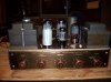
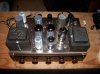
Follow the pictures by my Scott 210-E20171218_231732.jpg
20171218_231723.jpg20171218_231942.jpg20171218_231742.jpg20171218_231913.jpg

This E version is a Laboratory amplifier too. Are 27 Watts, which 2 EL34 outputs tubes.
Regards
 

Attachments

  • 20171218_231732.jpg
    20171218_231732.jpg
    47.1 KB · Views: 3
Well.
I buyed 2 PIO caps 0.022uf X 400V, to use in this Scott.
what's the best place on the circuit that I could use them to get a gain in sound quality?
Thank you.
 
The power tube current flow in the circuit pictured is fixed; it is set by the resistor coming off the cathodes of the power tubes and also runs through the filaments of three small signal tubes.

Before thinking about making an adjustment, you would do well to measure how hot or cool they are running as is. The best way to do this is to put a one ohm or a ten ohm 1% resistor off each power tube cathode, before it gets to the next component. Measuring the voltage drop across these resistors will give you “cathode current”. With that, and the plate voltage, you can calculate the plate dissipation - the be all/end all number that “adjustng the bias” effects.

A little soldering, a little math, and some careful probing, and you’ll find what you are looking for.

The easy way? If he tubes aren’t red-plating, leave them alone. In a well designed circuit, in-spec components it should he fine.
I will add resistor off each power tube cathode. I did it in a my Bell receiver in the past. I will post result here.
Thank you.
 
so in the entire world there are no schematics for the 210-E! I have one too and can not find a schematic. of course I can change out old caps and hope it works but... the tube sockets have hand written labels on them for the tube types which do not match the 210F or the 210D the 210D is closest to the tube lineup but ..... If anyone has found one of these that would be great. if not looks like the best bet is to follow the 210D schematic and pray!
 
Wow great. can you load any higher resolution? it comes up VERY pixelated at this end regardless of how I try to save it to the computer. it is nice to know that one exists! Thanks So much for digging this up!
 
Last edited:
If you send me a PM with an email, I can send a PDF and JPG of it. Looking at the JPG it is very clear. I guess the AK software dummied it down.
 
Back
Top Bottom