• Please note that Audiokarma will be offline briefly for updates early on Monday morning, September 28th.

Sencore SG165 - AM/FM Analyzer - Repair

MarantzRefrb

Super Member
I mostly stay in the Marantz forum, but this SG165 thread probably doesn't belong in there - until this is repaired.

I've been trying to climb the ladder of knowledge when working on the early-mid 70's Solid State Marantz's. I've come to the AM/FM alignment portion of this journey, and I realize this one requires a lot of research and practice.

I recently purchased this SG165 from eBay, the seller says he used it for many years successfully, and then one day it had no more FM output. I got this for an amazing price as a result, but it will require repair.

Here's what I'm working with:
ZpGcGQI.jpg


kEBxSJz.jpg


BC5CD0z.jpg


btJZpjB.jpg


Ilye0Vz.jpg


p9hVs4Z.jpg


SAnEds2.jpg


WnzRID2.jpg


E5YDUfQ.jpg


lfcHfOI.jpg


This one is really clean and complete. The knobs all work, none are internally broken, the power LED comes on, and that's as far as I could get tonight.

Has anyone here used or repaired one of these before?

I just got this today, so I haven't studied the manual yet. Is there a quick test you could outline for me, that would demonstrate the problem this unit may have, specifically the seller said it no longer has FM output.

Thanks!
 
Register to hide this ad
Search YouTube.. There is a decent video of a guy doing a restoration on the SG165. Also quite a bit on the antique radio forum.

I have one but only used it a few times. Moved on the the SG80. I found the SG165 to be a decent system for tuner repairs but not quite at the level of getting the most out of an alignment. The distortion spec is not quite low enough. Also you nearly always need a distortion meter to make FM alignments.

That being said if you can get it working and have a way to measure distortion you can certainly do alignments with the SG165. It's also easily sold if you decide to upgrade.
 
I had one for a while, the main problem with mine was that the 'Fine' micro volt control (actually a 75Ω resistive 'L' pad) was bad and I couldn't find a suitable replacement.
If I remember correctly, it was designed for automotive radio/stereo repair, at least that was what the shops I worked at used it for.

Tom
 
Search YouTube.. There is a decent video of a guy doing a restoration on the SG165. Also quite a bit on the antique radio forum.

I have one but only used it a few times. Moved on the the SG80. I found the SG165 to be a decent system for tuner repairs but not quite at the level of getting the most out of an alignment. The distortion spec is not quite low enough. Also you nearly always need a distortion meter to make FM alignments.

That being said if you can get it working and have a way to measure distortion you can certainly do alignments with the SG165. It's also easily sold if you decide to upgrade.

Yes, I've been looking at the Kiethly 2015, and Quant Asylum QA401, which I hear can be used in conjunction with the 165 for good results. Might not be the best choice possible, but I'd like to fix this SG165 first and foremost, and go from there.

I've seen a couple videos on Youtube, fixing the broken dial shaft and the like, but I have a different problem than the videos I've seen, according to the seller. I'll RTFM.
 
I saw one comment in the antique radio forum where the output was blown when it was improperly used on a tube tuner. I think some transistor was replaced and it was fixed.
 
I hear the FET's can be problematic too. I'll need to get a correct test setup first, then try to find out what's not working. Thanks!
 
I found the source of my confusion regarding the cabling for this SG165. All of the external components are 75 ohm female. I'm missing the main cable that goes from male BNC to 75ohm male.

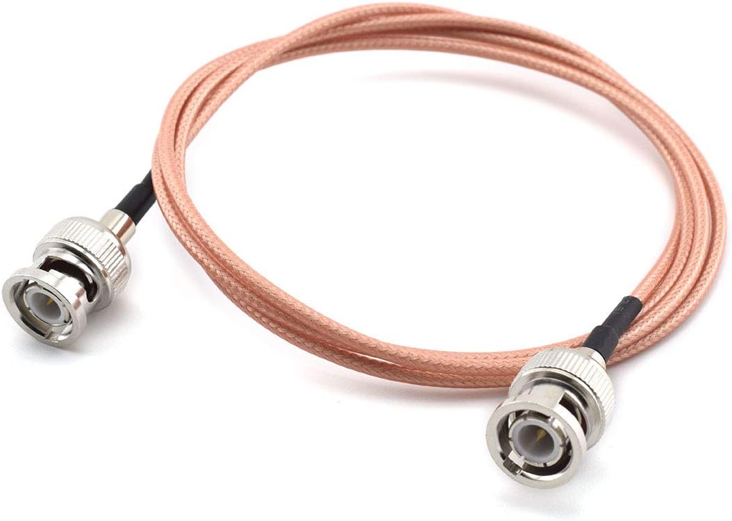
Had to make one. Went with a 3 foot male to male BNC cable, to connect to the female BNC labeled All Signal Output, on the SG165:
517iWFhd5sL._AC_SL1100_.jpg


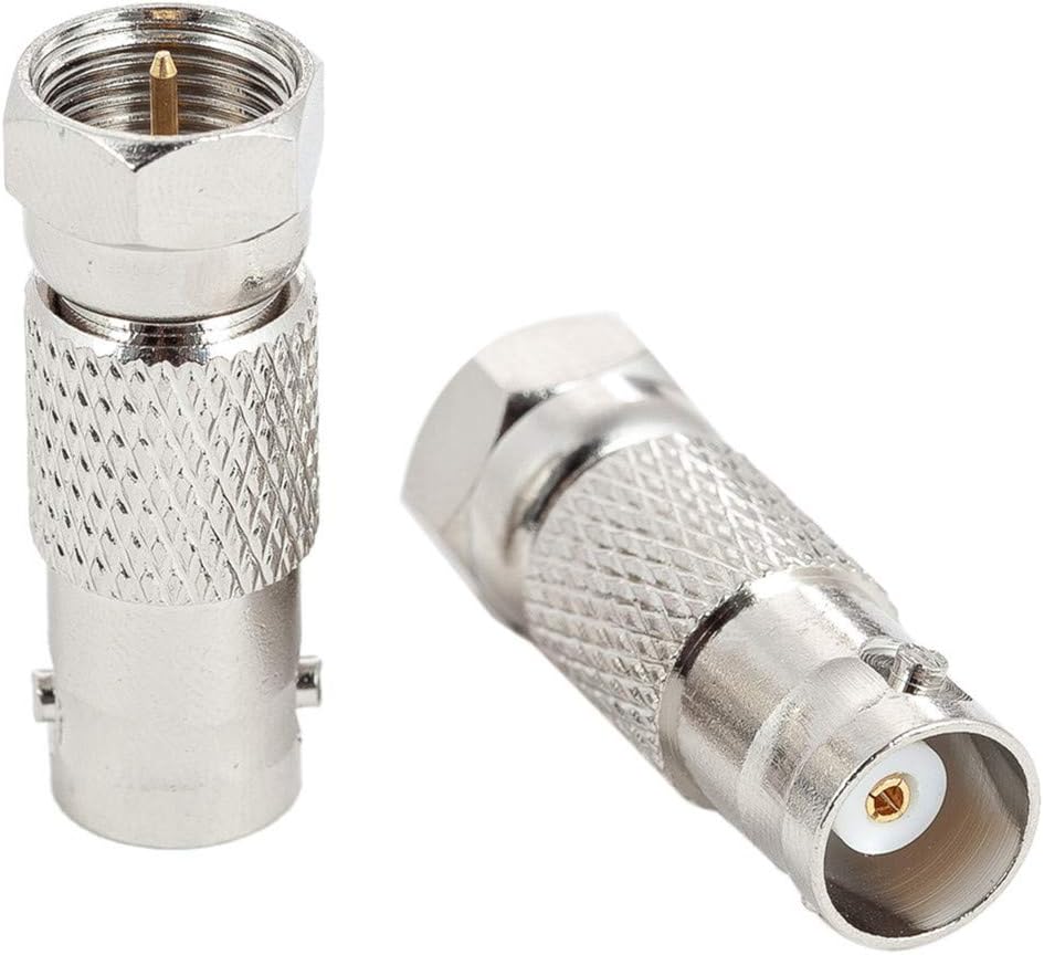
Adapter to 75ohm:
61%2BTukzdnwL._AC_SL1300_.jpg


Hope this works properly.

ZSONyeq.jpg


Ilye0Vz.jpg


I was able to connect the output of a 2215 to the SG165, the meters work well, so does the 8ohm dummy load.
Gaxmpcu.jpg


5M3LrGR.jpg
 
Last edited:
I'm sure you are aware that the cable needs to be 75Ω coax, I think the adapter you mention is BNC Female to 'F' male.

When I worked in test equipment calibration, we found most every between gender or type adapter caused about 1 dB of attenuation, which may or may not be a consideration in your application.

Tom
 
I was not sure of anything when I bought this, or received this :).

There are no pictures of the included components. The manual said an F cable, was what I needed.

You're saying I'd be better off with a 75ohm coax cable, of about 3 feet, with an adapter that has a female 75ohm coax on one side, to BNC male on the other, or:
https://www.amazon.com/gp/product/B07VVG22WB
71Q6JRYGnzL._AC_SL1500_.jpg


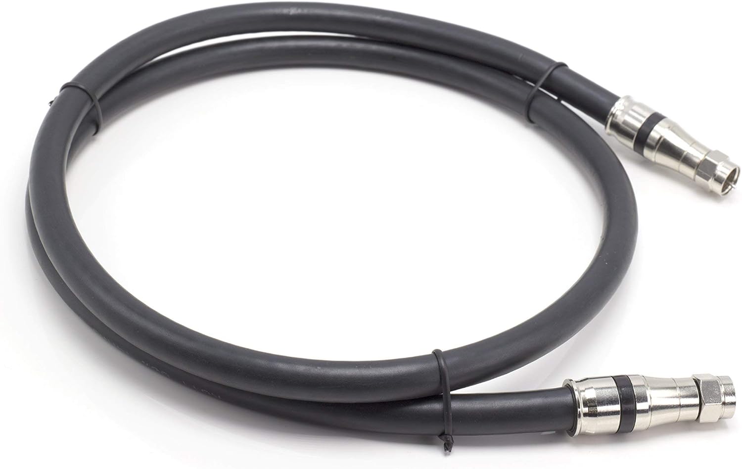
and shielded RG11 cable:
https://www.amazon.com/gp/product/B07B5JN89G
71LvaOd%2BZDL._AC_SL1500_.jpg


This would have less signal loss than the cabling option before this?

Also, do I need a BNC Tee, with termination plugs, to run the scope too?
 
I was not sure of anything when I bought this, or received this :).

There are no pictures of the included components. The manual said an F cable, was what I needed.

You're saying I'd be better off with a 75ohm coax cable, of about 3 feet, with an adapter that has a female 75ohm coax on one side, to BNC male on the other, or:
https://www.amazon.com/gp/product/B07VVG22WB
71Q6JRYGnzL._AC_SL1500_.jpg


and shielded RG11 cable:
https://www.amazon.com/gp/product/B07B5JN89G
71LvaOd%2BZDL._AC_SL1500_.jpg


This would have less signal loss than the cabling option before this?

Also, do I need a BNC Tee, with termination plugs, to run the scope too?


No need for RG11 cable, with the short length you will be using it is not needed and you would curse it every time you tried to bend it out of the way.

The small diameter BNC to BNC cable you showed earlier will be just fine even with an adapter. What is important is that you use a 75 ohm cable. Really makes no difference which end is adapted.

In the big scheme of things a DB or so loss is not a real big deal. It's FM radio not rocket science :bigok: no need for NIST level calibrations here.
 
I mostly stay in the Marantz forum, but this SG165 thread probably doesn't belong in there - until this is repaired.

I've been trying to climb the ladder of knowledge when working on the early-mid 70's Solid State Marantz's. I've come to the AM/FM alignment portion of this journey, and I realize this one requires a lot of research and practice.

I recently purchased this SG165 from eBay, the seller says he used it for many years successfully, and then one day it had no more FM output. I got this for an amazing price as a result, but it will require repair.

Here's what I'm working with:
ZpGcGQI.jpg


kEBxSJz.jpg


BC5CD0z.jpg


btJZpjB.jpg


Ilye0Vz.jpg


p9hVs4Z.jpg


SAnEds2.jpg


WnzRID2.jpg


E5YDUfQ.jpg


lfcHfOI.jpg


This one is really clean and complete. The knobs all work, none are internally broken, the power LED comes on, and that's as far as I could get tonight.

Has anyone here used or repaired one of these before?

I just got this today, so I haven't studied the manual yet. Is there a quick test you could outline for me, that would demonstrate the problem this unit may have, specifically the seller said it no longer has FM output.

Thanks!

This is a TV/Radio shop grade generator. Not low enough distortion or of suitable grade for working on a Marantz of that era, or better class HiFi unit. You need something more like a Sound Technology alignment generator for HiFi gear. The TV shop where I worked as a grunt technician in high school had the Sencore. For table radios and most radio/phonograph consoles up to RCA, Zenith, and Magnavox, it worked well.
 
I've read the SG165 works great for AM, mono FM, and can be made to work for FM, and FM MPX. I plan to restore this SG165, and make it even tighter, and with better range, as was mentioned on Antique Radios.

If you have something positive to contribute, or a real world example, I'm listening.
 
I've had two of them, and still have one. Both were converted to BNC connectors in all locations, front-panel speaker inputs, and minimal repairs/upgrades in the power supply. One needed a shaft repair for the VC, but both aligned in very nicely after the alterations and repairs.

When you dive in, this may be useful: https://audiokarma.org/forums/index.php?threads/only-on-audiokarma.829530/#post-12214897

You were fortunate to receive all the probe filters with the unit.
 
Thanks for the reply! I would really like to have the manual in PDF format, but for some reason the link is not working for me.
http://www.wwdsltd.com/files/SencoreSG165OperationManual.pdf

I just got my cable/adapter today for the SG165, and it seems to have no output FM or AM. I also noticed the Microlvolt Output knob is cracked and the shaft feels bent, slightly wobbly. Time to start taking it apart.

EDIT: Found the PDF here:
https://www.download-service-manuals.com/en/manual.php?file=Sencore-7924.pdf
 
According to the SG165 Troubleshooting steps, I have a problem with the power supply, to begin with.
NqV2kVy.jpg


I'm getting 28V + and - on C105 and C106, more than double the expected value. When I unplug the PSU molex to the RF board, I have 31V + and -.
OgZrFh5.jpg


I don't see the rectifier they're talking about just yet, I'll remove the PSU and start checking components.
 
I've read the SG165 works great for AM, mono FM, and can be made to work for FM, and FM MPX. I plan to restore this SG165, and make it even tighter, and with better range, as was mentioned on Antique Radios.

If you have something positive to contribute, or a real world example, I'm listening.
They're not that great, but ya gotta start somewhere!

There's a guy that goes by xraytonyb on YouTube. He uses one to modulate a synthesized generator. That may prove to be a good upgrade path for you looking forward.
 
I have seen the video by xraytonyb, thanks! Unfortunately, he had different problems than I'm experiencing.

Also, I get it, the SG165 is not the greatest unit for this purpose, I've obviously been told that enough times now, but I already knew that when I bought it. And yet I'm still here to fix this SG165.

The problem I've got with this one, is that the Power Supply unit is producing too much voltage, need to figure out which component is responsible. What would allow more than twice the voltage to occur in this board?

Thanks!
 
According to the SG165 Troubleshooting steps, I have a problem with the power supply, to begin with.


I'm getting 28V + and - on C105 and C106, more than double the expected value. When I unplug the PSU molex to the RF board, I have 31V + and -.
OgZrFh5.jpg


I don't see the rectifier they're talking about just yet, I'll remove the PSU and start checking components.

SG.jpg

Based on your picture vs the schematic you have C105,106 marked wrong. They are 1000uF it looks like they should be C103 and C108 which would have the unregulated voltages on them.

C105, 106 would be the small blue caps and should have the regulated voltages on them. If the schematic is correct and you were actually measuring C102,108 then when unplugging the load the unregulated voltages would rise.
 
Last edited:
This PSU looks to be untouched, completely original. The eBay seller said it worked perfectly as is, for many years.

I measured the 1000uF, and they are really high, one was 1588uF 0.24ohm ESR, this is the other:
gQEdWsB.jpg


The troubleshooting guide points to the CR105 diode, but I don't see it:
9HTANyE.jpg


UyTdCE2.jpg


XQLV1D2.jpg
 
Back
Top Bottom