• The move to the new server is done. There are some software and database maintenance updates in process. This has us passing the hat around to help out. We appreciate any donations. Seriously, even a dollar helps. The payment page may be found here - https://www.audiokarma.org/support.html

Sharp RP-117 with a new problem

FrankFIII

New Member
The Sharp RP-117 TT has been working fine all summer. After a short time of non-use due to trying to prepare for winter, I went to use it again to play some Christmas albums. While it did play, initially, I thought I had not pressed the both sides button or pressed the repeat button. So I dismissed that as operator error and tried again. This time I was watching it and the TT simply reset itself and went to a state as if I just put an album in but did not press play. I tried again with another album and it worked perfectly so I thought is was just a fluke or operator error by me fat fingering something. I tried to run it again yesterday. This time it happened again. The unit reset itself and went back to the home position on side A. I also noticed this only happens while it is warming up in temperature. When it has been running for a while it seems to behave. When the event/rest does happen, the LEDs and the lamps on the from panel seem to blink out or go out briefly in a blink of an eye. When the lights comes back on, depending on the duration, I may have no LEDS or 2 LEDS on at the same time for tonearm position or it just continues on without a change. If long enough, the unit resets like a power outage. This could be tricky to track down. anyone ever see this type of behavior?
 
Register to hide this ad
While I don't think i am entirely finished with this turntable, I have found the filter cap in the LV supply had 1.4V P-P ripple on it. While I did not have an exact match for C401 - 2200 uF 35V I did have a 1000 uF 35V that I temporarily tacked in to see how it improves operation. I have a replacement cap on order.
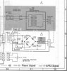
Before I put the temp cap in place, the 19.8V supply was low at 15.6V. with the 1000 uF cap in place it is at 17.9V. Not there yet but closer. I was REALLY surprised when I was looking at the circuit for the LV power supply. I found the transformer, FW bridge and filter cap are HOT all the time while the unit is plugged in. The ON-OFF switch merely removes bias on the base of Q101 to remove turn off the 10V supply and in turn the 5V supply.
Even more surprising is the fact that the power transformer T101 that I mentioned above is hot all the time is NOT fused on the primary side in any way. There is an internal fuse in T101 on the SECONDARY side AND an additional external fuse F401 1.5A 125V that protects the output as well.
 
Last edited:
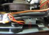
I finally got the replacement cap in. The voltage on the 19.8V supply came up about 1.2V to 19.1V While it did seem to lessen the time the display would blink out and the unit would reset, it was perplexing to see it would still do it once or twice per album while the unit was cold. Once warmed up, it would work fine. I kept running the unit with the cover off and late last night another gremlin appeared. It could be the cause of the unit resetting itself. As it was playing on side "B" I kept hearing the sound like something under tension then breaking free in the form of a "clicking" sound. I cued the tonearm and was holding the buttons down for forward and reverse the have the tone arm travel. As the tonearm was at about 5/8 of the way across the record, I heard the tension sound again, but this time it sounded more mechanical (can't explain that but that's the way it was to me) I reversed direction of the tonearm and it moved ok, I got a flashlight and while observing operation, I hit the forward button. What I found have me concerned and really puzzled. While in a forward direction, the drum and encoder wheel were pitched at an angle not straight up like they are supposed to be. At that same moment I spotted this, VR103, the 20K potentiometer that rotates via a gear off of the the drum and encoder wheel was twisting in the opposite direction causing the gear on the pot to skip a tooth. It took me a while to get it apart, but I found the shaft on VR103 was seized up. The pot has an aluminum shaft and an aluminum body that is threaded to mount it. I think this control should be watched and the shaft lubricated to keep it from freezing up. I used a light 3 in 1 oil then moved it as much as I could possibly 1/16" for fear of twisting it off. It gradually gave in and started to rotate. Stiff at first, but eventually full rotation. I then used a synthetic oil for a more lasting effect. While looking at the unit, I thought the LEDS on the front panel moved to indicate the position of the tonearm via pulses from the encoder wheel. NOT THE CASE. The tonearm position LEDS are driven off of the wiper of this pot that is rotated via a gear from the the drum and encoder wheel - nothing more. If you have the gears for the pot disengaged, you can rotate the pot like a volume control and watch the position LEDS run the entire range by the varied input voltage.
 
Mr FIII - Found this interesting as I have the same unit. Got any pictures to better illustrate what you describe here? Would be quite helpful. Thanks.
 
I too, have this unit, (being linear tracking nuts, seems like MRL-audio & I buy the same stuff a lot) mostly for the coolness factor, since I got it for free, and for the life of me I can’t remember if I upgraded any of the caps, but I will check this weekend since I am waiting for parts on my current project anyway. Funny enough, I last used it to play Christmas albums, too! 2 LPs from the Time-Life set that was bought still sealed at a thrift for $0.50 is still in it! Though mine works fine most of the time when warm, it had been a little stubborn from cold at times & I know I never lubed that pot either. I have a pair of new styli here waiting to be installed. I’m glad I plugged it in to my switched outlet on the receiver, too! Most power buttons do kill power from the mains to the transformer somehow, so that’s not too smart of Sharp.
 
Last edited:
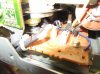
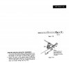
It took me a while but I finally got some pictures. Had trouble getting these macro shots to be in focus. VR103 is located at the back of the unit at the point where the audio output is located. As you can see it is buried very well. The adjustment screw is used to slide the gear on the pot away fro the drum so it can be indexed as needed, then slide back into place for re engagement. I have also included the page from the service manual that described how to adjust the position of the pot It mentions a 25 cm LP record, but I don't know where to locate one with that dimension and move the forward button until the needle is above the lead-in area and adjust the pot to get the reading indicated. The Sharp part # for the pot (VR103) is RVR-B0275AFZZ - 20Kohm.

Sharp117a.jpg Sharp117b.jpg Sharp117c.jpg
 
GRRRRRHHHH! Got it all back together and the middle red wire broke off of VR103. Now I have to dig back into it to re-solder the one wire. Unless I can work my way in there somehow while holding the wire, holding a light and a soldering iron all at the same time. Let me see what I can get done.
 
I generally have to use the third hand tool when I solder this type of stuff. Not always easy though... Good luck and sorry that happened. I feel at fault since I asked for the pictures which you graciously provided. Thanks for that.
 
MRL_Audio - no problem not your fault. It may have been hanging by a thread before. I'm sort of glad it happened now and not 6 month to a year down the road, where I would have to re-invent the wheel.
 
perryinva, if you are going to change C401, I got mine from Mouser and used a Cornell Dubilier - CDE 2200uF 35V, MFG Part No: 228CKS035M . It cost $ 0.81 plus tax and shipping. Since this section is always hot, unplug is first, then depress the power switch to drain off any voltage that is left.
Sharp PS.jpg

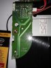
C401 is held to the bottom/underside of the PCB with the LP Record Sensor with some type of rubber cement. Once I unsoldered the pins, I used a razor blade to cut it free of the PCB. When putting it back in I ended up applying 2-3 dabs of clear RTV. This should hold nicely. For easier access, if you remove the 1 screw in the location I have circled in red. The whole PCB with the LP sensor lifts right off to provide ample room to work.

Good Luck!

Sharp Cap.jpg
 
Back
Top Bottom