Plimpington2
Super Member
Folks,
Time once again to be burdened by my Shell 2020P “Manhasset” integrated amplifier on my bench off and on for 3 years now. I have gotten the line stage working great. The phono stage, on the other hand, has the most horrific hum imaginable. Almost ever effort to quiet it down has failed. I rebuilt the whole thing. I even ran a grounding bus to one point for the whole amp. No joy.
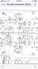
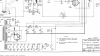
Each channel uses 1/2 of a 12AX7 and 1/2 of a 12AU7. RIAA is passive and of the feedback variety. For whatever reason, only the front tube is DC heated. This off the common cathode of the output tubes. Runs around 9V. I could adjust this a bit by changing out the cathode resister, but I hardly think that’s the issue.
The front tube IS the problem, I feel. It begins to hum when my finger gets close to it. Humming reduces, but still bad, when I touch the chassis. I am going to rebuild it again, and change the switching scheme so that the phono stage sits entirely in front of the source selector (right now, it kinda sits “between” it. It’s an odd layout). The phono input will go directly to the first grid of the phono stage (with suitable load resister to ground, of course).
AND, I’m going to rectify the heaters of both tubes. The question is, is there a realistic limit to how much current I can draw through the common cathode of the OP tubes? What is the practical consequence of pulling, say, 600ma through the cathodes rather than just 300ma? AND, just WHERE does this current come from anyway? OR, am I better off throwing a bridge and capacitor across the back end of the heater chain and hope for the best?
Time once again to be burdened by my Shell 2020P “Manhasset” integrated amplifier on my bench off and on for 3 years now. I have gotten the line stage working great. The phono stage, on the other hand, has the most horrific hum imaginable. Almost ever effort to quiet it down has failed. I rebuilt the whole thing. I even ran a grounding bus to one point for the whole amp. No joy.
Each channel uses 1/2 of a 12AX7 and 1/2 of a 12AU7. RIAA is passive and of the feedback variety. For whatever reason, only the front tube is DC heated. This off the common cathode of the output tubes. Runs around 9V. I could adjust this a bit by changing out the cathode resister, but I hardly think that’s the issue.
The front tube IS the problem, I feel. It begins to hum when my finger gets close to it. Humming reduces, but still bad, when I touch the chassis. I am going to rebuild it again, and change the switching scheme so that the phono stage sits entirely in front of the source selector (right now, it kinda sits “between” it. It’s an odd layout). The phono input will go directly to the first grid of the phono stage (with suitable load resister to ground, of course).
AND, I’m going to rectify the heaters of both tubes. The question is, is there a realistic limit to how much current I can draw through the common cathode of the OP tubes? What is the practical consequence of pulling, say, 600ma through the cathodes rather than just 300ma? AND, just WHERE does this current come from anyway? OR, am I better off throwing a bridge and capacitor across the back end of the heater chain and hope for the best?