• The move to the new server is done. There are some software and database maintenance updates in process. This has us passing the hat around to help out. We appreciate any donations. Seriously, even a dollar helps. The payment page may be found here - https://www.audiokarma.org/support.html

Sherwood S-4400 - selenium rectifier replacement problem

basplin

Active Member
Recently got one of these all recapped and cleaned up. Turned it on and it blew it's fuse. I'm thinking it could be the old selenium rectifier in there. So I ordered up some 3A 1000V silicon diodes and put a couple of those in according to how (I thought) they're in the schematic. I first put it on a DBT, and the bulb dimmed. Great, so I pulled it into the wall. Turned it on, and the 150uf cap it was attached to turned into a mini steam geyser in about 3 seconds.

So, at the risk of looking like an idiot....what happened here? I'm still learning (obviously) but I'm not sure where things went wrong.

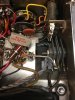
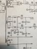
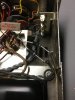
Attached are photos, before with the SR and with the new diodes, as well as the snapshot of the schematic (M1 is the SR).

Thanks!
 

Attachments

  • IMG_3166.JPG
    IMG_3166.JPG
    50.8 KB · Views: 40
  • IMG_3158.jpg
    IMG_3158.jpg
    64.2 KB · Views: 38
  • FullSizeRender.jpg
    FullSizeRender.jpg
    50.2 KB · Views: 38
Register to hide this ad
Looks proper, as long as the joint of the two silicon diodes go to the can cap and not to ground. Hard to tell from the pic. I would install a terminal strip to make those connections more physically secure though.

If you rebuilt the caps for the bias supply, be aware that the + lead goes to chassis, and the - lead goes to the terminals. Its opposite the usual configuration.
 
Did you add resistance to the circuit? The Selenium diode has greater internal resistance, reducing initial turn on current and has larger volt drop. You would normally need to add resistance to get the same -23V. If the 150uF cap was marginal it is possible that the increased current or higher voltage was too much for it.
 
There's also the possibility that the cap was already bad. That could explain the blown fuse... the selenium rectifier could not 'overcome' the low impedance of the shorted cap (so the bias was down, and the overcurrent in the outputs blew the fuse), but the silicon diodes could- and the cap blew up...
 
Welp, I'm a dingus. I just checked and I actually put the bias caps in backwards.... smh. No wonder it exploded. But hey, at least I got the diodes right, ha!

That's a good point about the resistance though, tinkerbelle. How much would you add, and where exactly would you add it?

Thanks for chiming in, Gordon. The cap was brand new, and I'm pretty sure its my "expert" installation that did it in! However, I'm not entirely sure that the old selenium rectifier was still good. Probably good to replace it any how.

Thanks everyone!
 
resistor usually would go between the first cap and the rectifiers. How much depends on how high it is. Try 10 ohms 5 watts and see what you get on each side of it. From there its easy to calculate the proper value resistor. Low voltage selenium isn't as lossy as HV, so it probably doesn't need to be a very high value.
 
resistor usually would go between the first cap and the rectifiers. How much depends on how high it is. Try 10 ohms 5 watts and see what you get on each side of it. From there its easy to calculate the proper value resistor. Low voltage selenium isn't as lossy as HV, so it probably doesn't need to be a very high value.

Yep, selenium rectifiers usually lose about 1 volt per section (if it's a plate rectifier, count the number of plates, and subtract one- that's the number of sections it has) when new, and somewhat more than that when old. A silicon diode is usually more like .6v, period.

If it's not got plates- selenium rectifiers usually can handle around 25v per section. So, just divide the bias voltage by 25, and round up to the next integer, and you usually have the number of sections it has inside.

Multiply the number of selenium sections by 1 volt per section, and you will have the amount of voltage drop you want to reproduce, with the added resistor.

Regards,
Gordon.
 
Back
Top Bottom